8
Customer Helpline
0844 801 3652
Preparing to Operate the Chainsaw
Step 2 - Assembly instructions
INTRODUCTION
ASSEMBLY REQUIREMENTS
This unit is designed for occasional homeowner use and should not be used for commercial purposes
or subjected to heavy continuous use.
Your new chainsaw can be used for a variety of projects such as cutting rewood, making fence
posts, felling small trees, limbing, pruning at ground level, and light carpentry.
Cut only wood or wood products with your saw.
Your new chainsaw will require adjustment of chain, lling the fuel tank with correct fuel mixture and
lling the oil tank with lubricating oil before the unit is ready for operation.
Read the entire user manual before attempting to operate your unit. Pay particular attention to all
safety precautions.
Your user manual is both a reference guide and handbook provided to furnish you with general
information to assemble, operate and maintain your saw.
WARNING: DO NOT start saw engine until unit is properly prepared.
WARNING: Always wear protective gloves when handling chain.
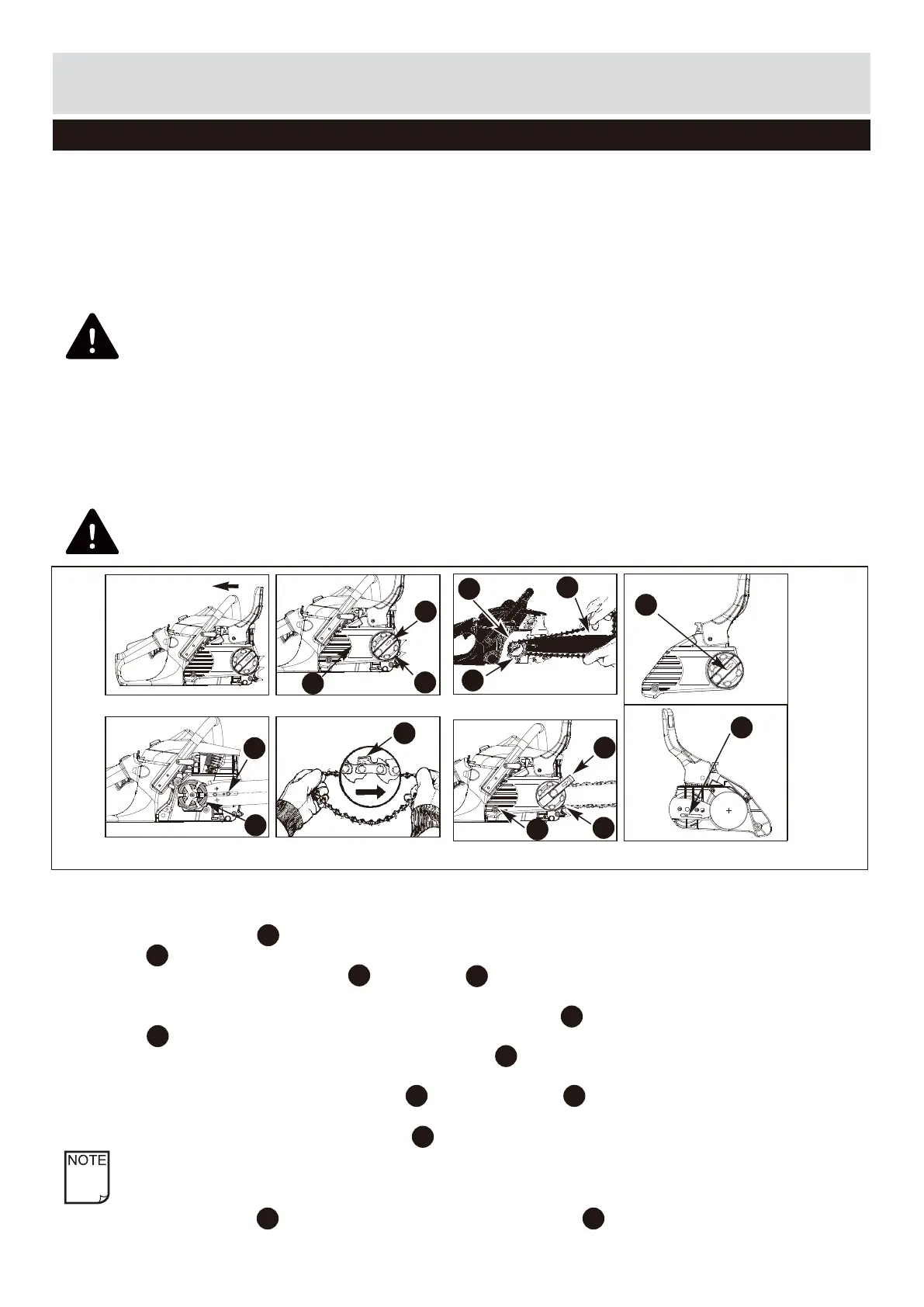
1. Place power unit on at surface.
2. Make sure the CHAIN BRAKE
®
lever is pulled back into the DISENGAGED position. (Fig.3A)
3. Loosen button slightly by turning knob counterclockwise and then turn the chain tension ring
counter-clockwise to relieve chain tension . (Fig.3B)
4. To remove the clutch cover , turn button counter-clockwise. (Fig.3B)
5. Remove saw chain from around the guide bar and the sprocket. Slide the guide bar, from the unit.
6. Place the slotted end of the guide bar over the bar bolt . Slide guide bar behind clutch drum
until the guide bar stops. (Fig.3C)
7. Spread the chain out with the cutting edges of the chain pointing in the DIRECTION OF
ROTATION (Fig.3D).
8. Slip the chain around the sprocket behind the clutch . Make sure the links t between the
sprocket teeth. (Fig.3E)
9. Guide the drive links into the groove and around the end of the bar. (Fig.3E)
NOTE: The saw chain may droop slightly on the lower part of bar. This is normal.
10. Turn the knob COUNTERCLOCK- WISE until the TANG is to the end of its travel. (Fig. 3F)
GUIDE BAR / SAW CHAIN / CLUTCH COVER INSTALLATION
Fig. 3A Fig. 3B
Fig. 3C Fig. 3D
Fig. 3E
Fig. 3G Fig. 3F
D
F
A
14
21
G
21
21
K
14
N
H
I
E
21
14
14
E
F
G
21 K
I
H
D
A