Connecting
20
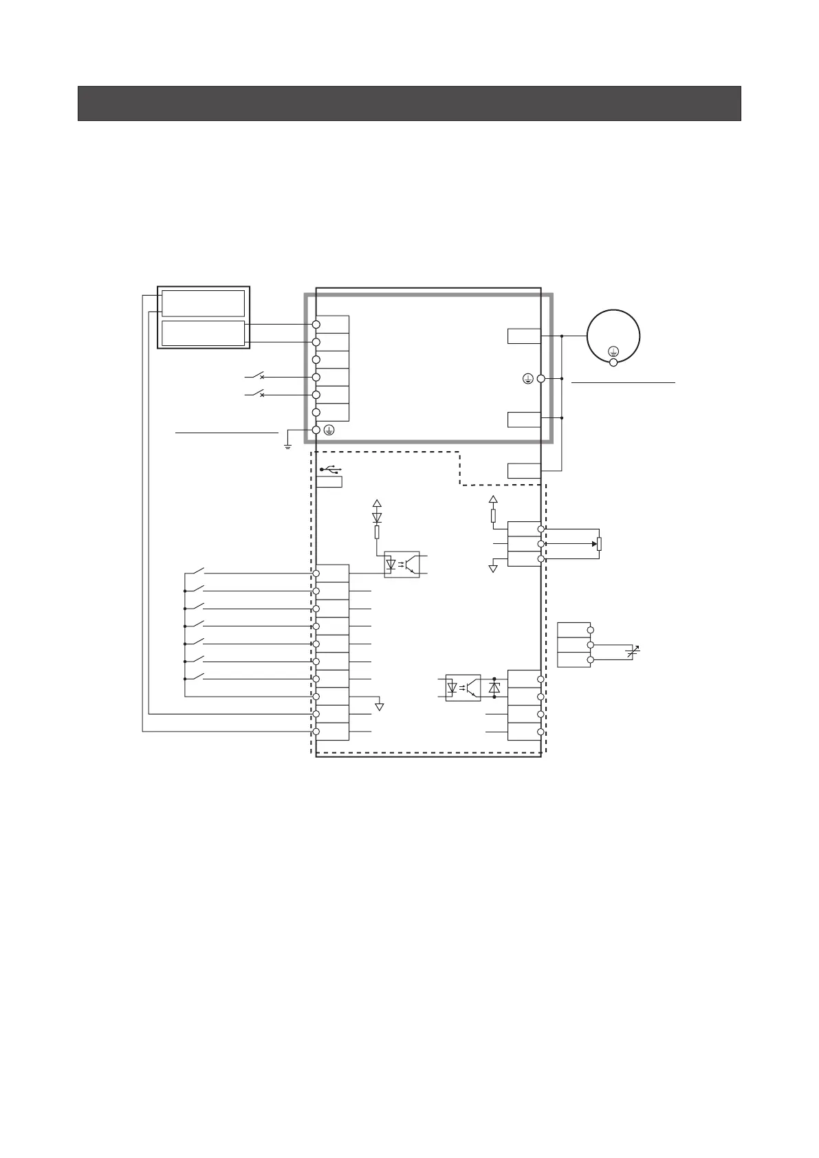
8. Connection diagram
Sink logic
z
When using the internal power supply
This is a connection example when the electromagnetic brake motor and the driver of single-phase 100-120 VAC are used, the
rotation speed is externally set, and the internal power supply is used for input signals.
I/O signals in brackets [ ] are set at the time of shipment.
Assignment of I/O signals
⇒
USER MANUAL
regeneration unit
R
Normally closed
150 °C (302 °F)
Connecting input signals
Connecting the
power supply
Speed setting by the
external potentiometer
14
L
Motor connector
Sensor connector
CN1
CN2
CN4
N
NC
RG2
RG1
NC
2
3
4
5
6
7
12
13
Command
voltage value
L
N
Circuit breaker
CN5
IN0 [FWD]
IN1 [REV]
IN3 [M0]
IN2 [STOP-MODE]
VH
VM
VL
14
12
13
CN5
N.C.
VM
VL
IN4 [M1]
0 V
+5 V
Main circuit
Control circuit
+5 V
Driver
8
9
11
10
IN5 [ALARM-RESET]
IN6 [MB-FREE]
IN-COM1
TH
TH
0 V
15
16
17
18
CN5
①
③
②
CN5
Speed setting by the
External DC voltage
(10 VDC or lower)
680 Ω
Grounding the driver∗
Be sure to ground.
Connecting
the USB
Connecting the motor
Motor
Grounding the motor
Be sure to ground.
Electromagnetic brake
connector
CN3
*
Be sure to ground. Refer to “3. Grounding” on p.16 for how to ground.
Refer to p.23 for connection of
output signals.