94
VCCX2 Controller Technical Guide
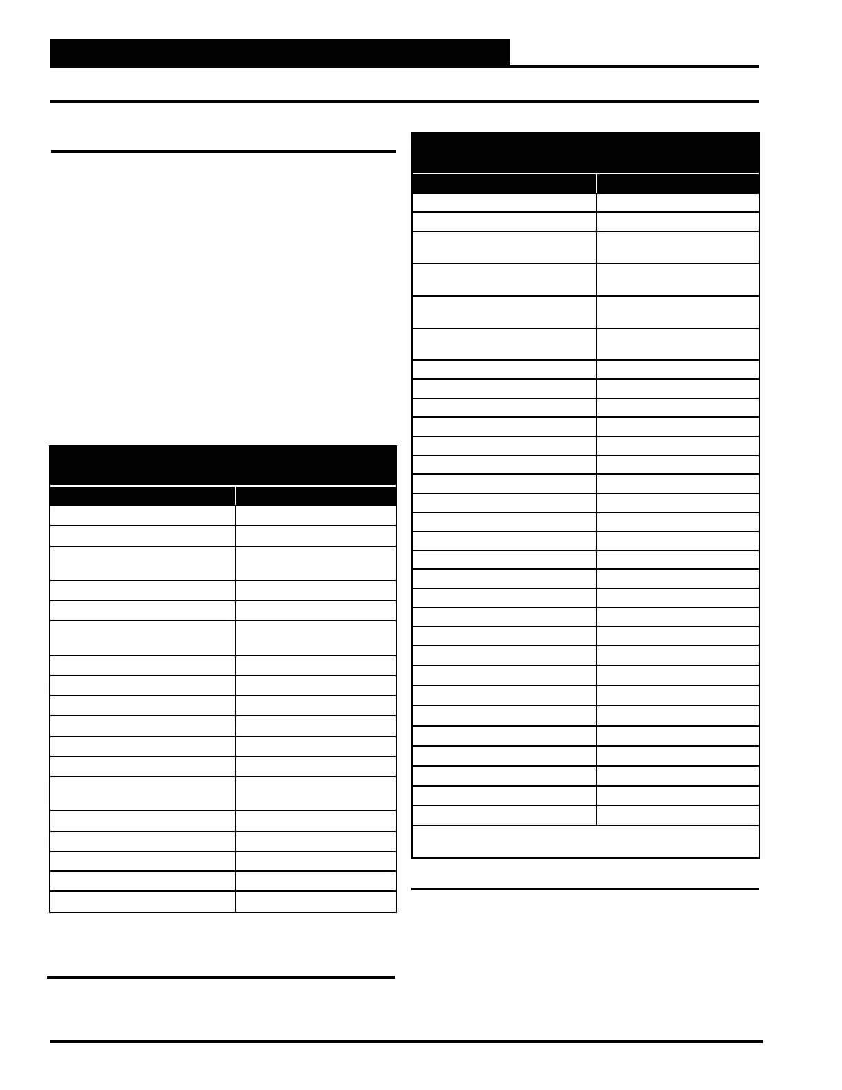
RSMZ MODULE TREND LOGS
(TYPICAL OF 4 RSM MODULES)
Item Description Log Abbreviation (Unit)
System Status SYSState (Bit String)*
System Command SYSCmd ((Bit String)*
A1 Compressor Modulating
Position
1Comp1Perc (%)
A1 Condenser Fan Position 1CondFan (%)
A1 Discharge Pressure 1DisPrs (PSI)
A1 Discharge Line
Temperature
1DisLnTmp (ºF)
A1 Suction Pressure 1SucPr (PSI)
A1 Suction Line Temperature 1SucLnTmp (ºF)
A1 Saturation Temperature 1SatTmp (ºF)
A1 Superheat 1Superheat (ºF)
A1 Expansion Valve Position 1EEV1Pos (%)
A1 Compressor Current 1CompCur (Amps)
A1 Compressor Status 1Comp1Stat
(Bit String)*
A1 Compressor VFD Status 1VFDStat (Bit String)*
A1 RSM Alarms 1RSMAlrms (Bit String)*
A1 VFD Alarms 1 1VFDAlrm1 (Bit String)*
A1 VFD Alarms 2 1VFDAlrm2 (Bit String)*
A1 Subcooling Temperature 1Subcool 1Subcool (ºF)
* Bit String and Enumerated Value information and interpretation is
explained in the paragraphs and tables at the end of this section.
Table 6: RSMZ Module Trend Logs
SEQUENCE OF OPERATIONS
RSMV/RSMD/RSMZ Trend Logs and Trend Log Enumerated Values
RSM Trend Logs
There can be as many as four RSMVs, four RSMDs, or six
RSMZs on a unit, with each RSM controlling up to two
compressors and condensers. These can be referred to as modules
1, 2, 3, and 4 or as modules A, B, C, and D. Various items
in the trend logs can refer to dierent modules and dierent
compressor/condensers on each module. For instance:
• 1A1: Stat refers to the status of Module 1/Compressor 1
• 4D1 would be Module 4/Compressor 1.
Likewise, 1SuctTmp1 refers to the suction (saturation)
temperature of Module 1/Compressor 1, while 3SucTmp2 refers
to the suction (saturation) temperature of Module 3/Compressor
2. Several trend log items will use this pattern to identify the
status of values related to certain modules and the compressors or
condensers on those modules. See Table 7, this page for RSMV
/ RSMD trend logs and Table 6, this page for RSMZ trend logs.
RSMV / RSMD MODULE TREND LOGS
(TYPICAL OF 4 RSM MODULES)
Item Description Log Abbreviation (Unit)
Compressor A1 Status 1A1Stat (Bit String)*
Compressor A2 Status 1A2Stat (Bit String)*
Compressor A1 Modulating
Position
1Comp1 (%)
Compressor A2 Modulating
Position
1Comp2 (%)
Condenser A1 Modulating
Position
1Cond1 (%)
Condenser A2 Modulating
Position
1Cond2 (%)
A1 Expansion Valve 1EXV1 (%)
A2 Expansion Valve 1EXV2 (%)
Condenser A1 Expansion Valve 1EXV3 (%)
Condenser A2 Expansion Valve 1EXV4 (%)
A1 Head Pressure 1HeadPr1 (PSI)
A2 Head Pressure 1HeadPr2 (PSI)
A1 Suction Pressure 1SuctPr1 (PSI)
A2 Suction Pressure 1SuctPr2 (PSI)
A1 Saturation Temperature 1SuctTmp1 (ºF)
A2 Saturation Temperature 1SuctTmp2 (ºF)
A1 Suction Line Temperature 1CoilTmp1 (ºF)
A2 Suction Line Temperature 1CoilTmp2 (ºF)
A1 Condenser Suction Temp 1CoilTmp3 (ºF)
A2 Condenser Suction Temp 1CoilTmp4 (ºF)
A1 Superheat 1SprHeat1 (ºF)
A2 Superheat 1SprHeat2 (ºF)
Condenser A1 Superheat 1SprHeat3 (ºF)
Condenser A2 Superheat 1SprHeat4 (ºF)
Superheat Setpoint 1SprHtSP (ºF)
Saturation (Suction) Setpoint 1CoilSP (ºF)
Leaving Water Temperature 1LvgWater (ºF)
A1 Discharge Temperature 1DisChg1 (ºF)
A2 Discharge Temperature 1DisChg2 (ºF)
Relay 1 Status 1Relay1 (Bit String)*
* Bit String and Enumerated Value information and interpretation is
explained in the paragraphs and tables at the end of this section.
Table 7: RSMV/RSMD Module Trend Logs