IM0973171 A 01 3
Fall protection
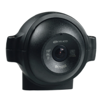
Cover plate
Cover plate
3 Bolts M8 x 20mm
Base
Socket head wrench
Base Plate
Socket head wrench
M5 Socket head screw
Fall protection
Installation Manual
1. Introduction
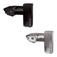
PT TIC (Pan Tilt Thermal Image camera) unit.
Pan & Tilt unit including thermal image camera. The PT TIC unit func-
tions via two stepper motors. These stepper motors are controlled by the
integrated micro-controller and input commands RS232 Visca-, Pelco D
protocol/P 9600 Baud rate. Commands for the PT TIC unit are sent via,
amongst other things, the Monitor 7” RLED Serial or Monitor 12” Serial.
Weather-, shock-, vibration-, corrosionproof. Weather-, shock-, vibration-,
corrosionproof.
2. Configuration
The space required for panning and tilting is:
Panning: 315mm.
Tilting: 370mm.
See also figure 7, page 6. When positioning the PT TIC unit, account must
be taken of the space required for panning and tilting. There must be no
obstacles in this space.
3. Mounting
The PT TIC unit has a base. Mount the PT TIC unit upright.
The PT TIC unit may not be mounted hanging or at a
angle! This would put too much pressure on the base
and mechanical components.
First demount two coverplates of the PT TIC unit, see figure 3.
To affix the PT TIC unit, use an pole bracket or a wall bracket. Or mount
the PT TIC unit directly to a metal surface.
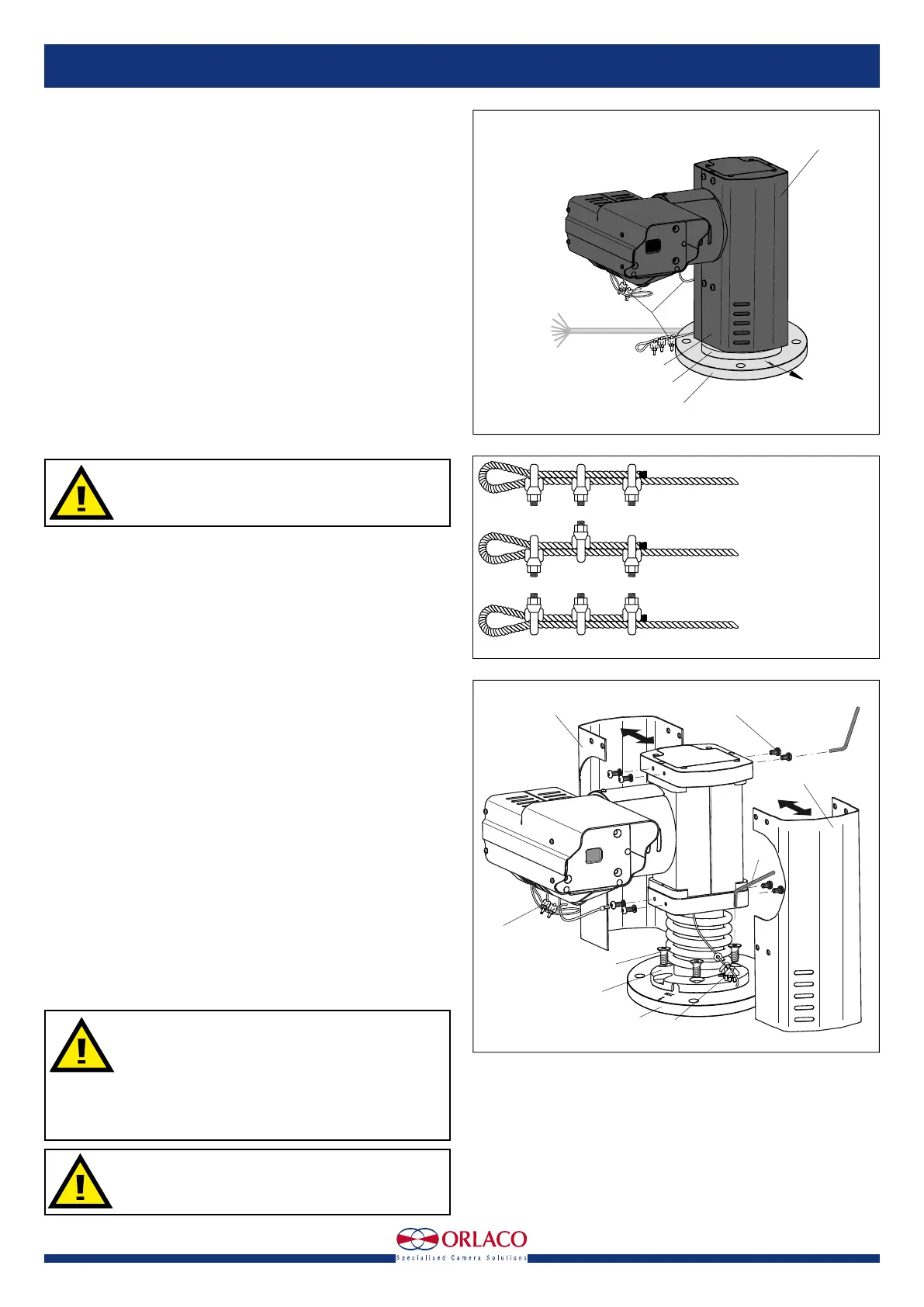
Note the starting position of the camera; this is indicated as the zero posi-
tion in figure 1.
Use a Allen key to secure the PT TIC unit with three M8 x 20mm Stainless
steel bolts(included). The base of the PT TIC unit has three recessed
holes. Mount the bolts (Hexagon socket countersunk head screws) from
the upper side of the base. For details of the size of the attachment points,
see figures 5 and 6. Mount the two cover plates back to the PT TIC unit.
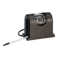
3.1. Mounting safety cables
Mount the fall protection to a fixed point. Use three cable clamps for
attachment. These cable clamps must to be installed correctly; see figure
2. Mount the safety cable from the camera to a fixed mounting point on
the same surface and height as the Base plate, see figure 4.
4. Operation
4.1 Overpressure in the enclosure
The enclosure of the Camera and PT TIC unit has a 1,4-bar overpressure.
4.2 Switching on and off
First of all, position the PT TIC unit in the zero position as indicated in
figure 1.
The PT TIC unit configuration is switched on by connecting the connector
cables to the power supply. It is switched off by disconnecting the con-
necting cable from the power supply. See figure 7.
Ensure that the PT TIC unit and other components of
the installation are closed so that it is not possible to
come into contact with moving parts.
Ensure that all parts are firmly fixed, stable and
secure.
Check that the power and connector cables are suit-
able for the system power supply.
Do not get too close to the PT TIC unit when the sys-
tem is switched on. There is a risk of injury.
Figure 1
Figure 3
Horizontal zero position
view direction
Cover plate
Cable Base
art. no 1221300
length 5,5m
Open
wired
Cable
fall protection
Base
Base plate
CORRECT
INCORRECT
INCORRECT
U-Bolt of all clips on
dead end of rope
Staggered clips
U-Bolt of all clips on
live end of rope
Figure 2