4 IM0973171 A 01
Installation Manual
5. Electrical installation
The PT TIC unit must be connected by trained electri-
cians. Under no circumstances should you make
connections that are not described in this manual.
5.1 PT TIC Cable specifications. Cable Base, Art no. 1221300
1 = Coax core Video
2 = Coax shielding Video GND
3 = Red Camera power, 18...30V/DC
4 = Black Camera 0V
5 = Red/White Pan/Tilt power
6 = Black/White Pan/Tilt 0V
7 = Green Serial 1 RS-232 TX
8 = Grey Serial 2 RS-232 RX
9 = Black/Gray Serial 0V
5.2 Example configuration
The following products are required for basic operation of the
PT TIC
unit, see figure 4.:
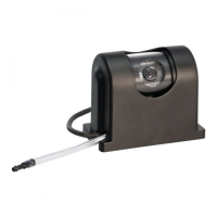
PT TIC unit Art Nr 0506972 or Art. no 0506982.
Monitor RLED 7", Art no 0208632.
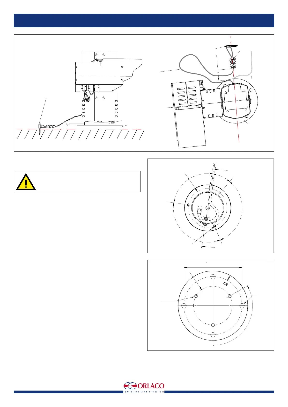
R = 50,0
M8 x 1,25 (3x)
horizontal zero position
Cable
120°
90°
30°
120°
Base
back side
Base plate
Top side
120° (3x)
M8 (3x)
R = 50,0
∅
Figure 6
R = 50,0
M8 x 1,25 (3x)
horizontal zero position
Cable
120°
90°
30°
120°
Base
back side
Base plate
Top side
150
120° (3x)
M8 (3x)
R = 50,0
∅12 (4x)
Figure 5
Camera cable
Top view
Base Plate
∅2 safety cable
from the camera
length 360-370
between camera
and wire rope
clamp
60 ±10
wire rope clamps (3x)
Mount the safety cable from
the camera on a fixed
mounting point on the same
surface and height as
the Base plate
Base plate
Base
Figure 4
Camera cable
Top view
Base Plate
∅2 safety cable
from the camera
length 360-370
between camera
and wire rope
clamp
60 ±10
wire rope clamps (3x)
Mount the safety cable from
the camera on a fixed
mounting point on the same
surface and height as
the Base plate
Base plate
fixed mounting point