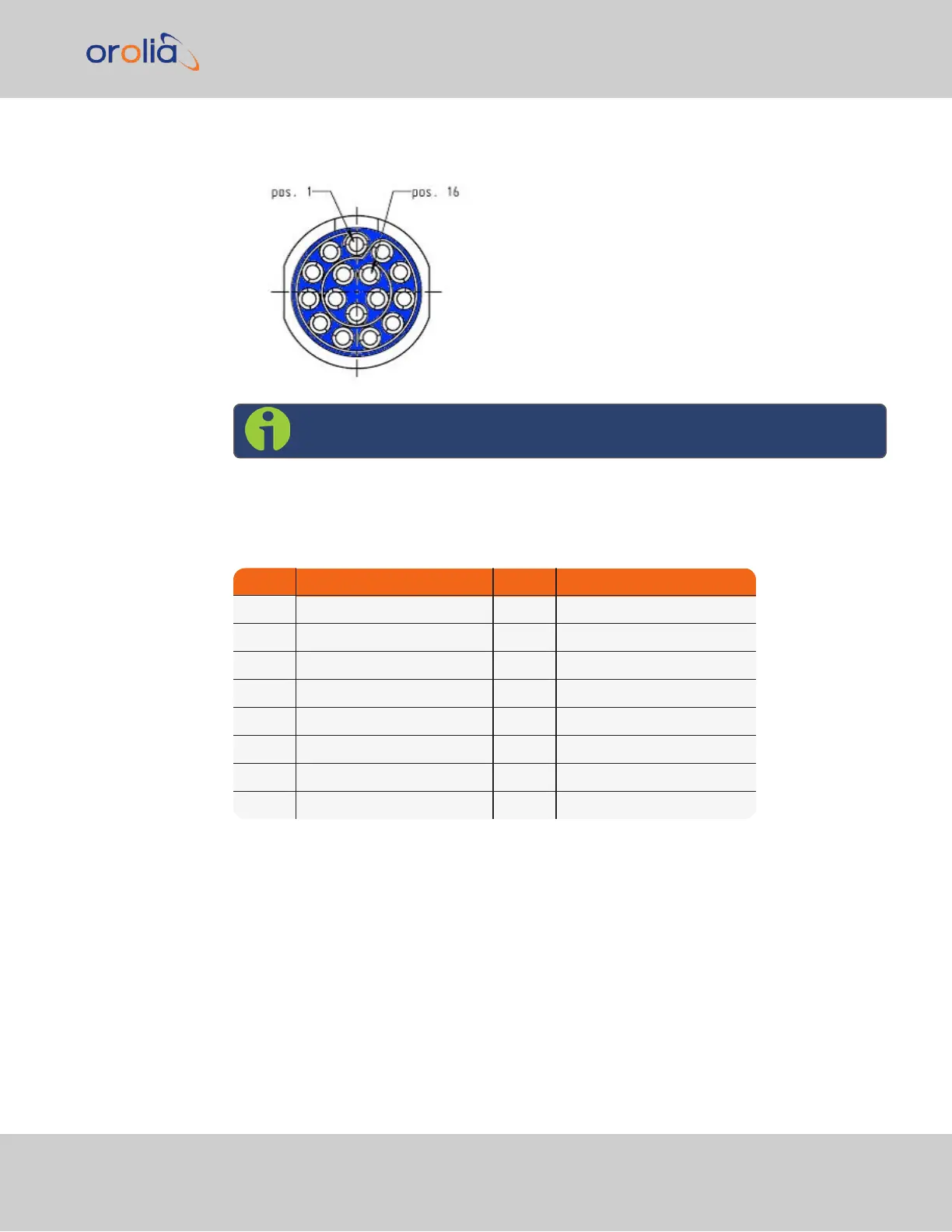
1.2.3 Ethernet Connector
Note: View in mating direction from front.
The Ethernet connector provides two 1GbE network connections, using 8 wires (pinout
below).
Table 1-5:
Ethernet connector pinout
Pin Signal Pin Signal
1 Ethernet_1 A+ 9 Ethernet_2 A+
2 Ethernet_1 A– 10 Ethernet_2 A–
3 Ethernet_1 B+ 11 Ethernet_2 B+
4 Ethernet_1 B– 12 Ethernet_2 B–
5 Ethernet_1 C+ 13 Ethernet_2 C+
6 Ethernet_1 C– 14 Ethernet_2 C–
7 Ethernet_1 D+ 15 Ethernet_2 D+
8 Ethernet_1 D– 16 Ethernet_2 D–
It is also possible to wire your connector to 100MbE, using only 4 wires. Contact Tech Sup-
port for more information.
1.2.4 Optional I/O Connector
The Optional I/O connector is used in conjunction with the Option Board that is available
for VersaSync. If the unit is not equipped with an Option Board, this connector is not used.
1.2 Connectors and their Pinouts
VersaSync Getting Started Guide Rev. 8 5