1.2 Connectors and their Pinouts
All of VersaSync's connectors are provided at the front panel of the unit, below the Status
LEDs.
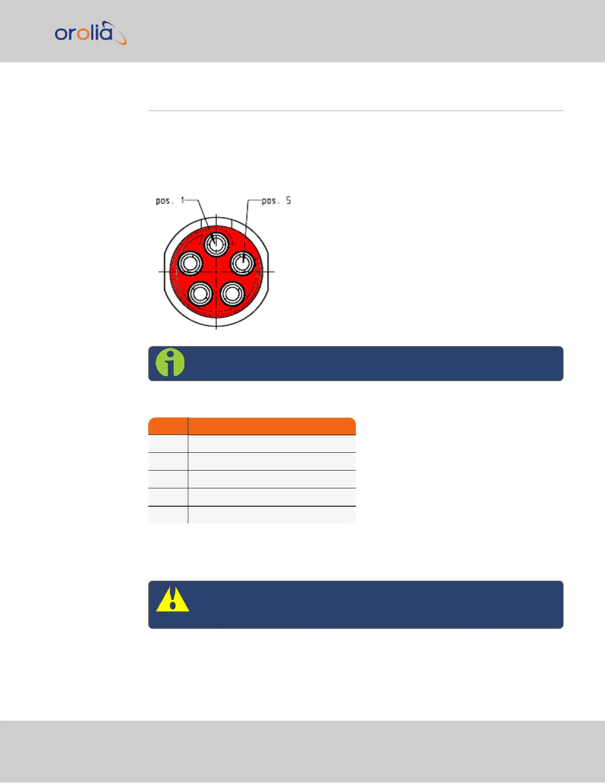
1.2.1 Power Connector
Note: View in mating direction from front.
Table 1-3:
Power connector pinout
Pin Signal
1 V
Main
(10 to 32V)
2 -not used-
3 V
Standby
(10 to 32 V)
4 GND (to Standby)
5 GND (to Main)
This product is designed to handle a maximum voltage of up to 32 V
DC
. Power supplies
with higher voltage or transient/ cranking power will require a power conditioner or surge
blocker.
Caution: Reversed polarity can blow an internal fuse that protects the
product from damage. Use care when building power cables.
1.2 Connectors and their Pinouts
VersaSync Getting Started Guide Rev. 8 3