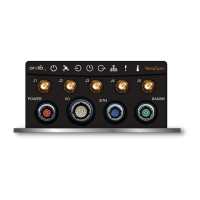
1.2.5 Coaxial Connectors
VersaSync offers five (5) coaxial connectors, three (3) of which can be configured at the
factory to accommodate requirements for e.g., additional 10MHz outputs. The minimum
configuration includes the GNSS antenna and a 10MHz sinewave output.
Unless otherwise ordered at the factory, all coaxial connectors (aside from the GNSS con-
nection) produce a 10MHz output that can be all disabled through the Web UI..
All coaxial connectors are standard SMA connectors. Avoid tightening past the maximum
torque.
ETHERNET connector wiring:
1 through 8: A Ethernet Connect, 4 pairs, 1000bT
9 through 16: B Ethernet Connect, 4 pairs, 1000bT
POWER connector pinout
1: V
Main
, 10 to 32 V
DC
2: -not used-
3: V
Standby
, 10 to 32 V
DC
(Standby Power)
4: Ground return, standby power
5: Ground return, main power
6
VersaSync Getting Started Guide Rev. 8
1.2 Connectors and their Pinouts