Osaka - F 10 - User Manual - V1 - PAG. 5
4.2.1 Electrical wiring diagram
Supply
1 32 4 65 7 98 10 1211
SPST-NO
INPUTS
OUT
(12 A max. for extr. conn. model)
Pr1
Digital
Input
Pr2
16 FLA
96 LRA
15 A Res.
EN
30 (15) A
61810
Out (H):
15 (15) A
5 FLA
30 LRA
12 A Res.16 (9) AOut (R): 10 (4) A
60730
EN UL
5. FUNCTIONS
5.1 ON/Stand-by function
Once powered the instrument can assume 2 different condi-
tions:
ON: Means that the controller uses the control functions.
STAND-BY:
Means that the controller uses no control function and
the display is turned off except for the Stand-by LED.
The transition between Standby and ON is equivalent to power
ON the instrument providing the electrical power
In case of power failure, the system always sets itself in the
condition it was in before the black-out
The ON/Stand-by function can be selected:
– With the key
pressed for 1 s if tUF = 3;
– With the key
pressed for 1 s if tfb = 3;
– Using the Digital Input if parameter iFi = 7;
5.2 Normal and economic operation
This tool allows to pre-set two different Setpoints, one Normal
- SP and one Economic - SPE.
Associated with each Setpoint there is the relative differential
(hysteresis): Normal - rd and Economic - rEd.
Switching between the two modes can be automatic or manual.
5.2.1 Normal/Economic operation selection
This function can be used when you need to switch two functional
temperatures (eg. Day/Night or week-day/week-end). The Normal/
Economic operation can be selected in manual mode:
– Using the
key if parameter tUF = 2;
– Using the
key if parameter tFb = 2;
– Using the Digital Input if parameter iFi = 6.
The Normal/Economic operation can be selected in automatic
mode:
– Elapsed the iEt time after the door has been closed
(Normal/Eco switching).
– At door opening if the SPE Setpoint is activated by iEt pa-
rameter (Eco/Normal switching).
– Elapsed the itt time after the door has been closed and from
the activation of SPE Setpoint by iEt parameter (Eco/Normal
switching).
To use this function, it is necessary to set the Digital Input as:
iFi = 1, 2 or 3.
If iEt = oF the selection of Eco/Normal modes via the digital
input is disabled.
If itt = oF the time-out switching from Eco to Normal mode is
disabled.
Switching to Economic mode is indicated by the label Eco.
When idS = Ec the Economic mode is pointed out with a fixed
Eco label otherwise the label Eco appears every 10 s alter-
nated to the display set with parameter idS.
The normal Set Point SP can be set to a value between the one
set with parameter SLS and the one set with parameter SHS
while the Economic Set Point SPE can be set to a value between
the one set with parameter SP and the one set with parameter
SHS.
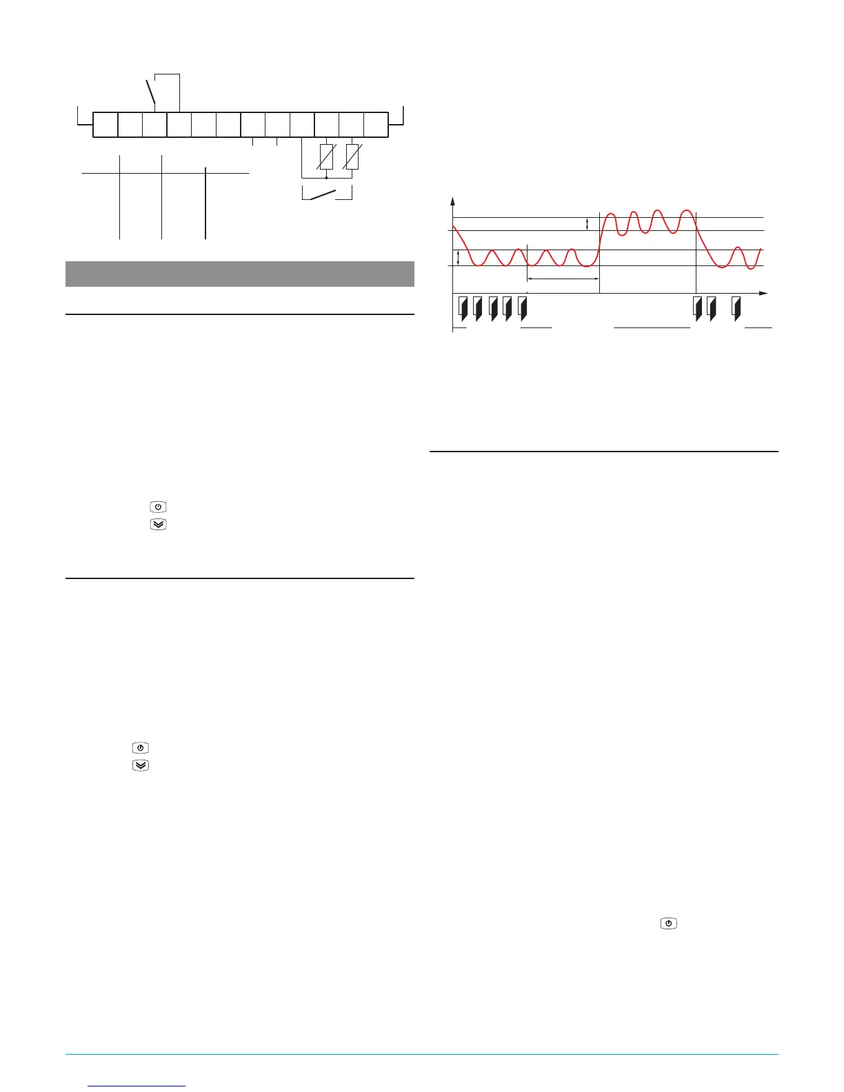
Temp.
Pr1
SPE
SP
Door
rd
rEd
iEt
time“Norm.”
DAY (Shop open) DAY (Shop open)NIGH (Shop closed)
“Norm.” “ECO”
Note: In the following examples the Set point is generally
indicated as SP and the differential as rd however the
instrument will act according to the Set Point and the dif-
ferential selected as active.
5.3 Measure and display configuration
With the iuP it is possible to select the temperature engi-
neering unit and the desired measure resolution (C0 = °C/1°;
C1 = °C/0.1°; F0 = °F/1°; F1 = °F/0.1°).
The instrument allows the measure calibration, which can be
used to recalibrate the instrument according to application
needs, The calibration is made by using parameters iC1 (input
Pr1) and iC2 (Pr2 input).
Parameter iP2 allows to select the instrument usage of Pr2
measure as:
Au Auxiliary probe;
DG Digital Input (see the Digital input functions).
If Pr2 input is not used, set iP2 = oF.
Using iFt parameter can be set a software filter for the measur-
ing the input values in order to decrease the sensibility to rapid
temperature changes (increasing the sampling time).
Through the
idS parameter is possible to set the variable normally displayed:
P1: Pr1 probe measurement;
P2: Pr2 probe measurement;
SP: Active Set Point;
EC: Probe measure if the instrument is in Normal Mode, the
label Eco if the instrument is in (Eco mode);
OFF: If the numerical display must be switched off (oF).
When is displayed one of the measures idS = P1/P2/Ec the iCU
parameter allows to set an offset that is to be applied only to the
displayed variable (all controls will always happen according to
the correct temperature value, changed only by the calibration
parameters).
Regardless of what is set at idS parameter, all the measure-
ment variables can be shown pressing the
key.
The display alternately shows the code that identifies the vari-
able (see below) and its value. The variables are:
Pr1 Probe 1 measurement;
Pr2
Probe 2 measurement (on/oFF if Pr2 is a Digital input);
Lt Minimum stored Pr1 temperature;
Ht Maximum stored Pr1 temperature.