Osaka - F 10 - User Manual - V1 - PAG. 6
The peak (min./max.) temperature values of Pr1 probe are not
stored in case of power failure and can be reset pressing the
for 3 s elapsed which, the display shows “---” for an instant to
indicate that the min./max. values have been erased and the new
peak is the temperature read in that moment
The system exits the variable dosplay mode after 15 s from the
last
key pressure.
It is also noted that the Pr1 probe display can also be changed by
defrost display function via the ddL parameter
(see the Defrost function).
5.4 Digital input configuration
The digital input function is defined using the iFi parameter
and
the action is delayed for the time programmed with parameter
iti. The iFi parameter can be configured for the following
functions:
0. Digital input not active;
1. Cell door opening with NO contact: at input closure (and af-
ter the iti) the instrument displays alternately oP and the
variable set at idS parameter With this mode of operation
of the digital input activates also the time set with param-
eter AoA elapsed which the alarm is activated to warn that
the door has been left open. In addition, at door opening,
the instrument returns to normal operation if it was in Eco
mode and the Eco mode activation was enabled through
parameter iEt
2. Similar to iFi = 1;
3. Cell door opening with output lock and NO contact: similar
to iFi = 1 but with output lock. At alarm door open inter-
vention AoA also the output is re-activated.
4. External alarm signal with NO contact: at input closing (and
after the iti time) the alarm is activated and the instru-
ment alternately shows on the display: AL and the variable
set with parameter idS;
5. External alarm signal with Control output disabled and NO
contact: at input closing (and after the iti time) the control
output is is disabled, the alarm is activated and the instru-
ment shows on the display alternatively AL and the variable
set with parameter ids;
6. Normal/Economic mode selection with NO contact: at input
closing (and after the iti time) the instrument switches
to Economic operation mode. Opening the digital input, the
instrument returns in Normal operation mode.
7. Instrument On/Off (stand-by) selection with NO contact:
at input closing (and after the iti time) the instrument is
switched ON while it is placed in Stand-by mode when the
digital input is open;
8. Do not use;
-1, -2, -3, etc. - Features identical to the above but obtained
through a NC contact and a reversed logic operation.
5.5 Temperature control
The instrument control is ON/OFF and acts on the output depend-
ing on the PR1 probe measuring, the Set Point SP (or SPE), the
Histeresys rd (or rEd) and the function mode rHC.
OUT (ot) OUT (ot)
SP
Temp.
Pr1
rd
time
offoff
SP
Temp.
Pr1
rd
time
ON
rHC = C rHC = H
offoffON ON ON ON ON
Depending on the function mode programmed with parameter
rHC the differential is automatically considered by the controller
with positive values for a Refrigeration control (rHC = C) or nega-
tive values for a Heating control (rHC = H).
In the event of a probe error, it is possible to set the instrument
so that that the output continues to work in cycles according to
the times programmed with parameter rt1 (activation time)
and rt2 (deactivation time).
If an error occurs on the probe the instrument activates the out-
put for the time rt1, then deactivates it for the time rt2 and
so on whilst the error remains.
Programming rt1 = oF the output in probe error condition
remains switched off.
Programming instead rt1 to any value and rt2 = oF the output
in probe error condition remains switched ON.
Remember that the temperature regulation function can be
conditioned by the Compressor Protections, Delay at power ON and
Defrost functions.
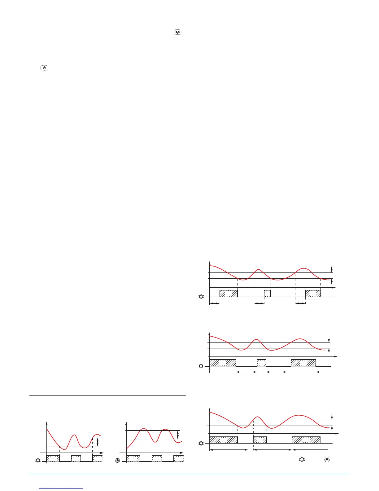
5.6 Compressor protection function and power-
on delay
The “Compressor Protection” function aims to avoid repeated
compressor start-ups controlled by the instrument in cooling
applications or otherwise can be used to add a timed control on
the actuator control output
This function foresees 3 time controls on the switching ON of
the output associated with the temperature control request
The
protection consists of preventing the output being switched
ON during the times set with parameters PP1, pP2 and PP3
and therefore that any activation occurs only after all times are
elapsed.
1. First control (parameter PP1) foresees a delay to output
activation (switching-ON delay).
SP
Temp.
Pr1
time
offoff off off
ON ON ON
rd
PP1 PP1
PP1
PP1
OUT (ot)
2. Second control (parameter PP2) foresees an inhibition to the
activation of the output by a time delay that starts when the
output is turning OFF (delay after switching-OFF).
SP
offoff off
ON ONON
rd
PP2 PP2 PP2
PP2
Temp.
Pr1
time
OUT (ot)
3. Third control (parameter PP3) foresees an inhibition to the
activation of the output by a time delay that starts when
the output was turned ON last time (delay between two
switching-ON).
SP
offoff off
ON ON
rd
PP3 PP3
ON
PP3
PP3
Temp.
Pr1
time
OUT (ot)
During the output inhibition the LED OUT (Cool or Heat )
blinks.