Osaka - F 10 - User Manual - V1 - PAG. 8
or they assume the values [SP + AHA] and [SP + ALA] if
the alarms are relative (AAy = 2 and 6).
AHA
SP
ALA
offoffoff
ON ON
Hi Lo
Temp. Pr1
time
AL
AAd
AAd
The maximum and minimum temperature alarms can be disabled
by setting the related parameters AHA and ALA = oF.
The temperature alarms are signalled lighting up the alarm LED
( ) and, if configured, also with the buzzer
5.8.2 External alarm from digital input
The instrument can signal an alarm external to the instrument
using the digital input setting iFi = 4 or 5. The instrument sig-
nals the alarm turning ON the
alarm LED ( )
and displaying AL
label alternated to the variable set with parameter Ids.
Mode iFi = 4 operates no action on the control output, while
iFi = 5 deactivates the control output at digital input interven-
tion.
5.8.3 Open door alarm
The instrument can signal the open door alarm coondition using the
digital input setting iFi = 1, 2 and 3. As the Digital input is acti-
vated, the instrument signals that the door is open showing on the
display the oP label alternated to the variable set with parameter
ids.
After the delay set with parameter AoA the instrument signals
the Open Door alarm with the configured devices (buzzer and/
or Output), lighting up the LED while showing the oP label.
At the open door alarm intervention are also re-activated the
inhibited outputs (compressor).
5.9 Function of keys and
Two of the instrument keys, in addition to their normal functions,
can be configured to operate other commands. The key func-
tion can be defined using the tUF parameter while the
key via
parameter TFb. Both parameters have the same possibilities and
can be configured to perform the following functions:
oF The key carries out no function;
1. Do not use;
2. Pressing the key for at least 1 s, you can sequentially select
a normal or eco operating mode (SP/SPE).
A selection has been made the display shows for about 1 s
the active set point code (SP or SPE);
3. Pressing the key for at least 1 s is possible to switch the
instrument from ON to Stand-by state and vice-versa;
4. Do not use.
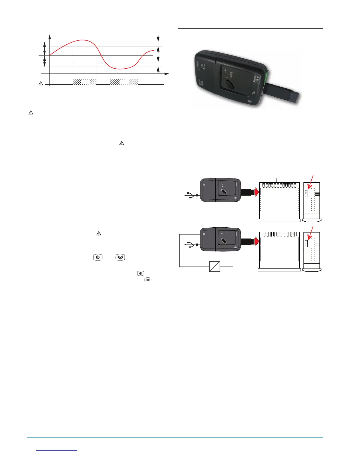
5.10 Parameters configuration by “KEY USB”
The instrument is equipped with a connector that allows the
transfer from and toward the instrument of the functioning pa-
rameters through the device KEY USB with 5 poles connector.
This device it is mainly usable for the serial programming of some
instruments which need to have the same parameters configura-
tion or to keep a copy of the parameters setting of an instrument
and allow its rapid retransmission.
The same device allows to connect a PC via USB with which,
through the appropriate configuration software for “
Universal
Conf or Osaka Set Up
”, the operating parameters can be configured.
To use the device KEY USB it is necessary that the device or in-
strument are being supplied directly or through the key.
AC supply
Supply adapter
12 VDC
Power supply
Enter
PWS
12 V
A B C
TTL
+
-
USB
to PC
USB
Enter
PWS
12 V
A B C
TTL
+
-
USB
to PC
USB
For additional info, please have a look at the KEY USB instruc-
tion manual.