CONNECTION
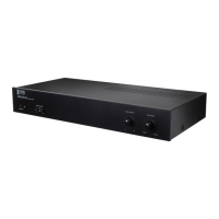
Connecting Optional Keypads
The Keypad kit comes with 6 POE enabled keypads. This allows for source control from each specic zone as well as
IR routing to the appropriate source devices once selected. The Keypad kit also comes with a hub that allows for all
6-keypads to be connected to the amp via Cat5e/6.
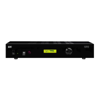
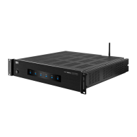
Without power being connected, connect a Cat5e/6 cable to the RJ45 port labeled
KEYPADS on the back of the NERO MAX/Control. We recommend terminating the
Cat5e/6 using the 568B standard.
At this point it is also important to address your keypads. Refer to the chart below which is also found on the PCB board of
the back of the keypad to set the dip switches according to the zone you would like it to control.
N E R O -M A X 1 2
2022-07-20
UL
62368
ZONE-1
ON ON OFF
1 2 3
ZONE-2
ON OFF ON
1 2 3
ZONE-3
ON OFF OFF
1 2 3
ZONE-4
OFF ON ON
1 2 3
ZONE-5
OFF ON OFF
1 2 3
ZONE-6
OFF OFF ON
1 2 3
CONNECTION
Connecting and Using the Zone Status Ports
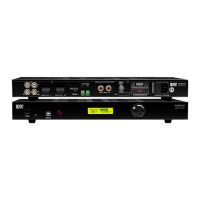
Connect the other end of the Cat5e/6 to the lone RJ45 port found on the front side of the Keypad Hub. Note that the
Cat5e/6 between the unit and the hub should only be between 7-10ft in length. The RJ45 ports on the back of the Keypad
Hub are not assigned but the single RJ45 port isolated on the bottom of the hub is reserved for cascading units.
Connect the other end of the terminated Cat5e/6 to the RJ45 port on the back of the assigned Keypad and installation is
complete. Complete zone and source control as well as IR and power are provided through the single Cat5e/6.
FRONT
Reserved for
cascading units
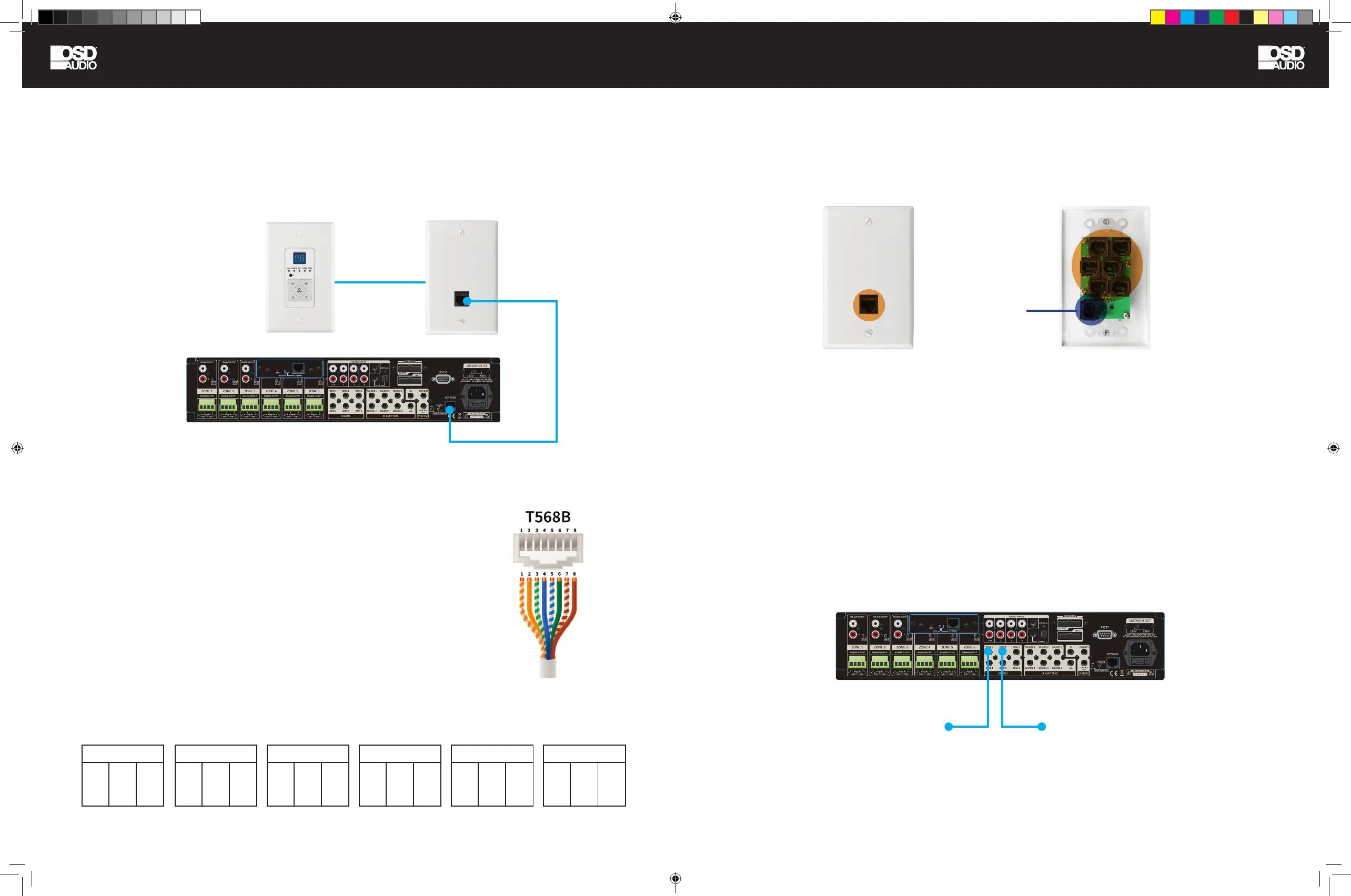
12V DC Trigger for ZONE-2 (for
example) to an External Amplier
12V DC Trigger for ZONE-1
(for example) to a Motorized
Projector Screen
BACK
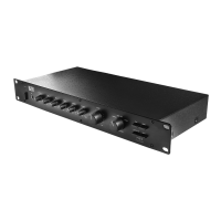
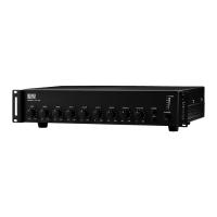
There are six 12V DC trigger outputs which correspond to the six output zones. When a zone is powered ON by the
NERO MAX/Control keypad, the corresponding zone sends 12V DC to the trigger output jack. The triggers can be used to
automatically switch peripheral equipment ON or OFF.
N E R O -M A X 1 2
2022-07-20
UL
62368
NERO MAX-CNTRL man.indd 12-13 11/14/22 11:37 AM
 Loading...