8
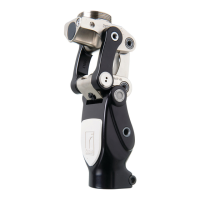
Patient Weight Colour Type
- kg (- lbs) Black Regular
- kg (- lbs) Red Firm
- kg (- lbs) Yellow Extra Firm
• Re-install the bumper cover by hooking the groove under the chassis
front and pushing the two pins into the chassis holes.
• Active patients may require a stiffer bumper
• Patients who have previously worn a prosthesis without a stance-
flexion feature may initially prefer a stiffer bumper.
• We suggest trying a softer bumper after two weeks of trial. This helps
the patient develop a security with the knee. Doing this will also help
make the transition to the stance-flexion characteristic more
acceptable.
STATIC ALIGNMENT
For safety, please make initial adjustments with patient standing between
parallel bars!
• Fit prosthesis and check for correct length.
• Make sure foot is flat on the floor, knee is in neutral position and
socket angles are correct.
• When the patient shifts weight onto the prosthesis, the geometric lock
is activated and the bumper should be slightly compressed. Modify
alignment if necessary.
• Explain function of stance flexion/geometric lock to patient. Ask
patient to activate it by stepping forward with prosthesis and
transferring weight onto heel.
• Patient should become accustomed to activating geometric lock and
resulting stance flexion movement.
• Knee cannot collapse as long as geometric lock is activated.
• Preset swing flexion resistance, Valve F (, Figure )
a. Sit patient on chair. Extend prosthetic knee. Let it fall into flexion.
b. Increase resistance of Valve F until a small bump observed at °
flexion angle.
DYNAMIC ALIGNMENT
The model knee provides smooth and fluid swing control during
normal ambulation and allows changes in cadence.
For safety, please make initial adjustments with patient standing between
parallel bars!
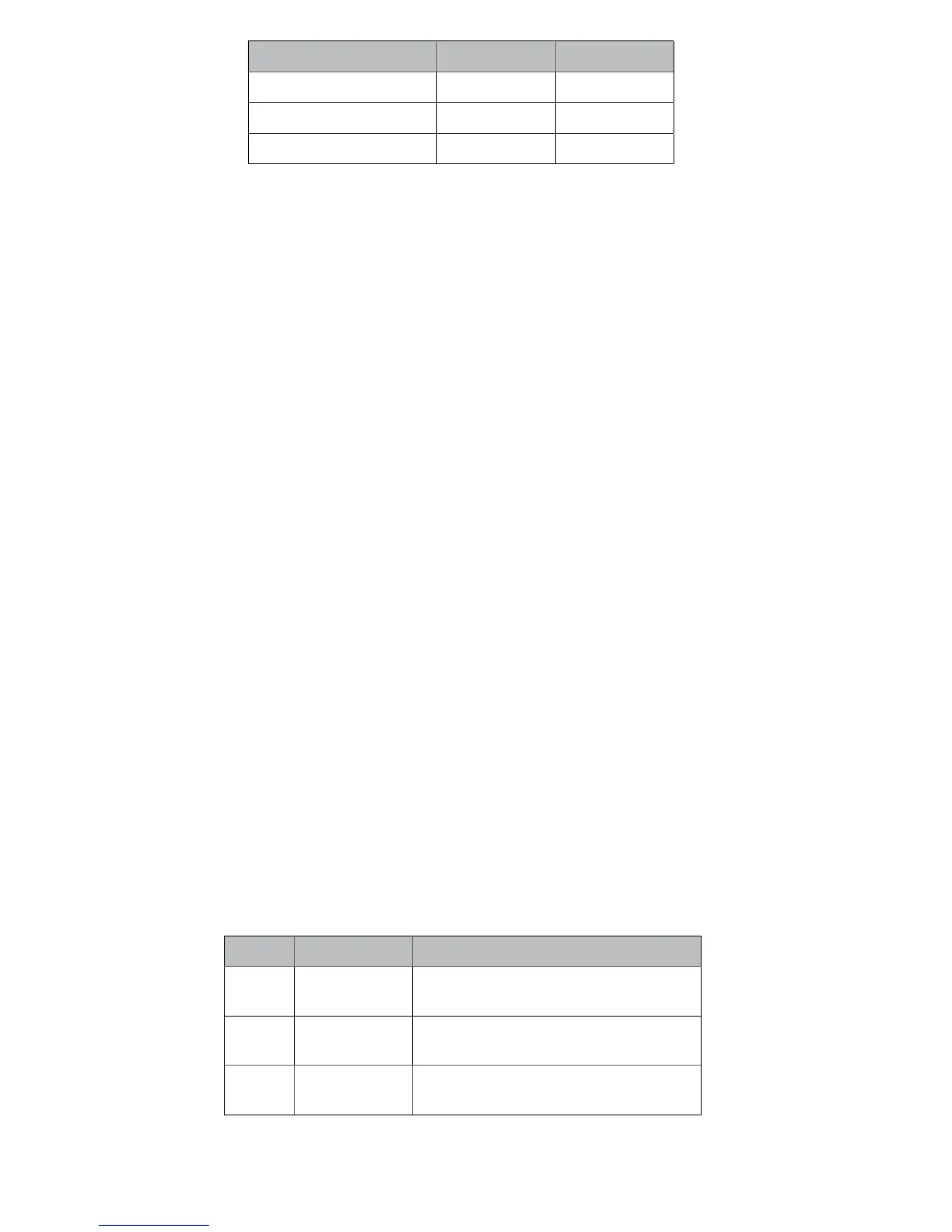
Valve adjustment – F, H, E (Figure )
Valve Factory setting Function
Valve F
¾ open
Aects swing exion resistance from °-
° (fast walking only)
Valve H
¾ open
Aects swing exion resistance from °-
° (slower walking)
Valve E ½
open
Aects whole swing extension resistance,
°- °
Use small flathead screwdriver for adjustment.