11
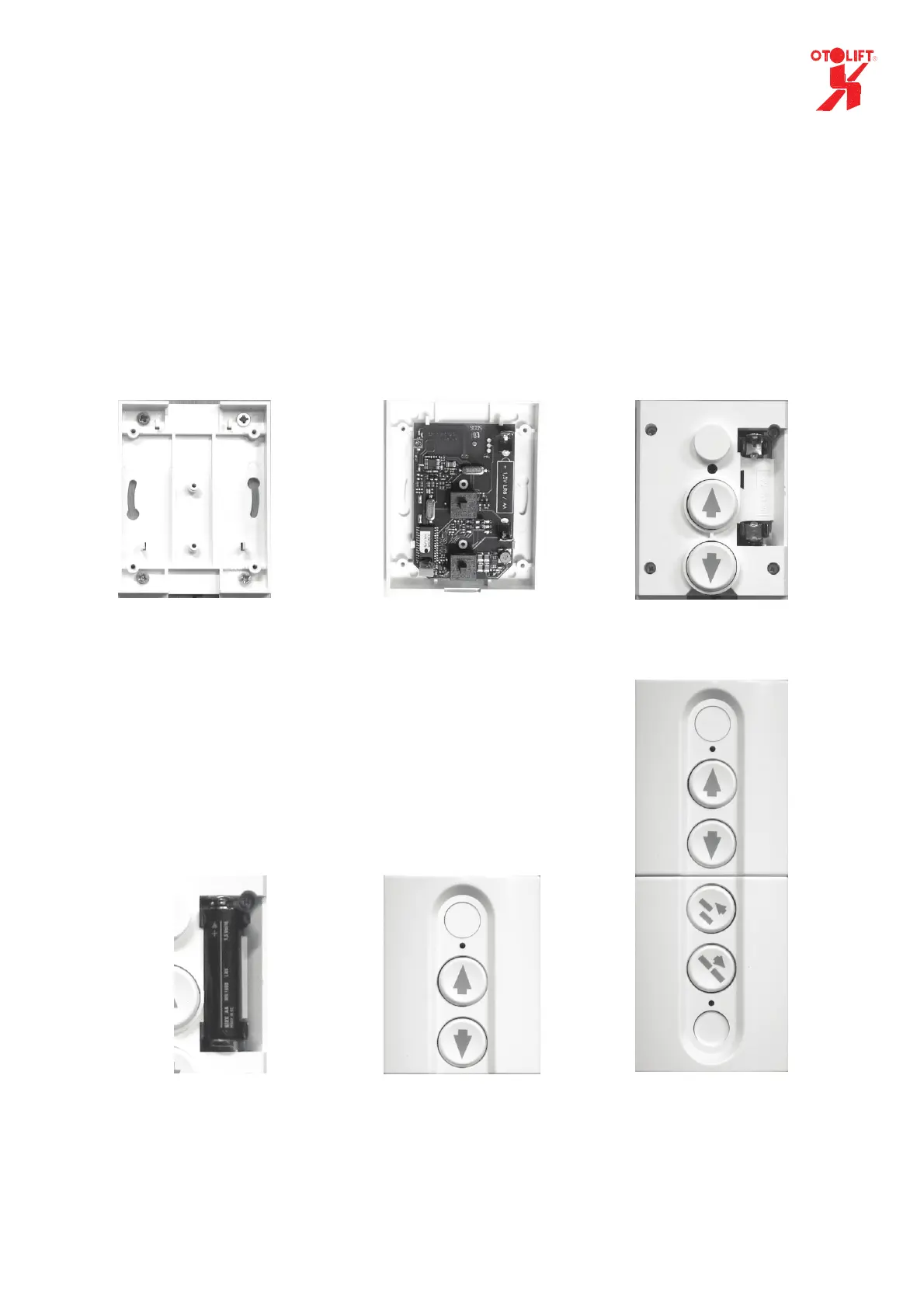
3. Remote Control assembly
• First of all an appropriate place has to be selected to install the remote control unit. From the
position where the unit is located, one must have a good overview of the major part of the
chair lift.
• Fit the base plate to a flat wall and clamp the PCB on the base plate.
• Attach the protection cap, holding the buttons, with the screws to the base plate. (4 pcs)
• Place the battery in the holder on the board. Pay attention to the correct +/- polarity.
Only use alkaline batteries: AA LR6 1,5 V.
• Click the cover over the base plate.
• Check the free functioning of the buttons.
In case the chair lift is provided with a sliding rail, you have to install an additional transmitter
below the remote control.
It is needed to control folding and unfolding the sliding rail.
Base plate Cap mounted
Standard or folding
hinge
Sliding hinge Battery connected
PCB mounted
 Loading...