3
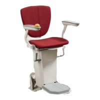
6. Put the cables through the rotating
disc.
Start with the 5 pole connector
(armrest)
Then the 3 pole, then the 2 pole
connector.
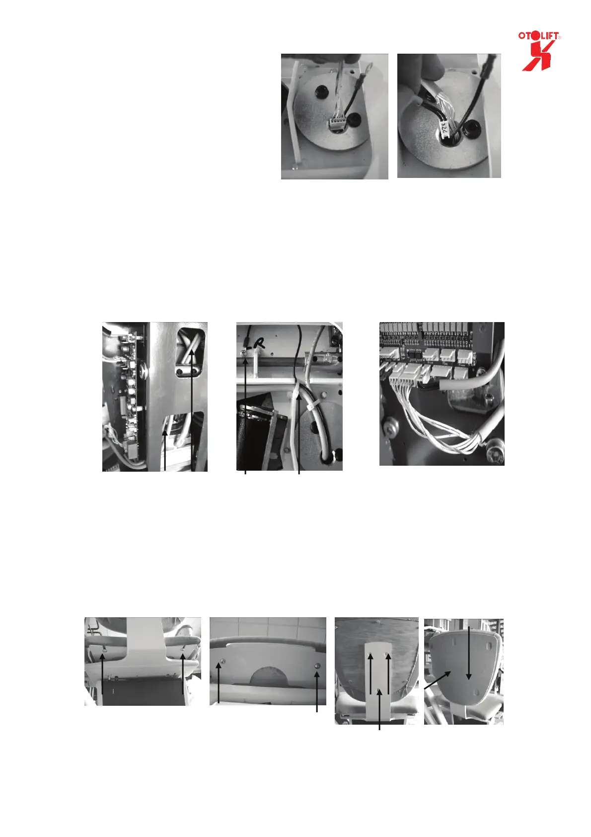
7. Guide the cables through the carriage to the PCB.
(Check if the mechanism of the footrest can not damage the wiring.)
8. Attach the cabling to the seatframe and connect the black wire to the seat frame by a m4 bold
(Check if the bolds of the rotating disc can not damage the wiring.)
9. Connect the wiring to the main PCB
(3 pole to X2a, 5 pole to x2b and the 2 pole to x2c)
10. Assemble the seat by using the 4 m6 x 16mm bolt and the 3 countersunk m6 x 16 bolt.
11. Mount the back of the back-seat by pushing the holes over the metal buttons and then slide it
downwards.
Both cables
connected
to PCB
Cables through
carriage
Cables attached to seat frame.
Black connected to frame
Bolts at the back
of the seat
Back of back-
seat mounted
Bolts at the back
of the back-seat
Bolts at the front
side of the seat
1 2