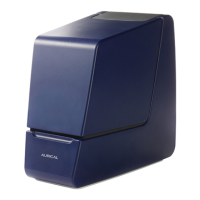
The AURICAL HIT is a device designed for Hearing Instrument Testing (HIT) and Coupler-Based Fitting, connecting via USB to a computer running the OTOsuite software. It is intended for use by audiologists, hearing instrument dispensers, and other healthcare professionals to test programmable hearing instruments. The user is expected to have basic knowledge of comparing test results with manufacturer specifications and detecting typical malfunctions.
Function Description
The AURICAL HIT, in conjunction with the OTOsuite HIT Module, allows for traditional hearing instrument testing according to ANSI or IEC test protocols. This ensures a consistent picture of every hearing instrument, regardless of manufacturer or type. With the OTOsuite PMM Module, it facilitates Probe Microphone Measurements in a coupler for pre-programming and pre-fitting hearing instruments without the client being present.
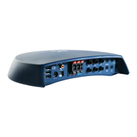
The device features a test chamber where hearing instruments are positioned for testing. The coupler assembly, a key component, consists of a coupler adapter, a 2 cc coupler cavity, and a coupler microphone. The 2 cc coupler cavity is manufactured in accordance with the ANSI standard. The coupler microphone can be used either directly in the AURICAL HIT or in an Accessory Box. The Accessory Box, when connected to the AURICAL HIT via a mini-jack cable, allows for wireless hearing instrument testing.
The AURICAL HIT includes a cable groove to secure programming cables, preventing the hearing instrument from being pulled out of place during testing. An elevation plate is provided to facilitate the positioning of wireless transmitters and body-worn hearing instruments, ensuring their microphones are centered in relation to the loudspeaker. Some models are equipped with a carrying handle for portability.
Important Technical Specifications
Operating Environment:
- Operating temperature range: 15 to 35 ºC (59 to 95 ºF)
- Maximum relative humidity: 80% for temperatures up to 31ºC (88 ºF), decreasing linearly to 50% relative humidity at 40 ºC (104ºF).
- Altitude: Up to 2,000 m (6,562 feet)
- Warm-up time: < 15 min
Transport and Storage:
- Temperature: -15°C to +55°C (5°F to 131°F)
- Air humidity: 10% to 90%, non-condensing
Battery Simulators:
The AURICAL HIT comes with a set of 4 color-coded battery simulators (Red, Blue, Yellow, Green) for powering hearing instruments and measuring power consumption. These correspond to battery types 10A/230, 675, 312, and 13, respectively.
Standards Compliance:
- CE-marked according to the Electrical Safety Directive IEC 61010-1
- Test standards: ANSI S3.22, IEC 60118-7
- EMC: IEC 61326-1
Usage Features
Installation and Connection:
The AURICAL HIT should be placed on a stable surface in a moderately quiet room to minimize ambient noise and comply with ANSI S3.22. Installation involves installing OTOsuite on a PC and connecting the AURICAL HIT to the PC via a USB cable. The device is powered by the PC and is automatically detected by OTOsuite.
Calibrating the Reference Microphone:
Otometrics recommends calibrating the reference microphone daily or weekly. This involves positioning the reference microphone 1-2 millimeters above the coupler measurement microphone, ensuring both are at the same distance from the main loudspeaker. Calibration is performed through the OTOsuite HIT module.
Positioning Hearing Instruments for Testing:
The positioning of the hearing instrument depends on its type (form factor). Key principles include aligning directional microphones along the loudspeaker axis and positioning the reference microphone as close as possible to the front microphone of the hearing instrument without touching it. Maximum permitted distances for the reference microphone are: 8 mm vertically (above), ±12 mm sideways (X axis), and ±3 mm back-to-front (Z axis).
Coupler Adapters:
Adapters (HA-2 for BTE and HA-1 for ITE, RIE, thin-tube) snap onto the coupler cavity. Hearing instruments are attached to the adapter outside the test chamber before snapping the adapter back onto the coupler cavity.
Traditional BTE Hearing Instruments:
This procedure uses the HA-2 adapter and BTE adapter tube for standard BTE hearing instruments with traditional ear molds.
Thin-tube Hearing Instruments:
This procedure applies to thin-tube hearing instruments, including Receiver In the Ear (RIE)/Receiver In the Canal (RIC) and pre-bent tubing, using the HA-1 ITE adapter. Acoustic putty can be used on the receiver wire to prevent vibration and feedback.
ITE Hearing Instruments:
This procedure applies to custom hearing instruments like ITE (In The Ear), ITC (In The Canal), and CIC (Completely In the Canal), using the HA-1 ITE adapter.
Telecoil Testing:
For telecoil testing, the hearing instrument is positioned as for BTE, thin-tube, or ITE instruments to achieve maximum field strength. AURICAL HIT automatically detects the orientation of the hearing instrument. After enabling telecoil mode in the hearing instrument, the lid is closed, and testing begins.
Hearing Instruments with Wireless Transmitters (e.g., FM):
When testing instruments with wireless sound transmission, the transmitter is placed in the AURICAL HIT, and the receiver is placed on the coupler microphone in the Accessory Box.
Performing a Standard Test:
- Launch the hearing instrument's fitting software.
- Launch OTOsuite and select the HIT module.
- Open the Test Selector and choose an ANSI or IEC special test.
- Fill in Hearing Instrument fields (if not using Noah).
- Position and switch on the hearing instrument.
- Connect the battery simulator if measuring Battery Consumption.
- Close the lid.
- Select desired tests in the Measurements table.
- Click "Start" to begin the test sequence, following on-screen instructions.
- Individual tests can be redone by clicking "Start" next to them.
Testing the Directional Microphone:
While true directional measurements require anechoic chambers, AURICAL HIT performs a functional test. The signal (Broad Band Noise, 750 Hz - 5 kHz, 70 dB SPL) is presented from the front and then the back of the hearing instrument. The "Directionality Adaptation" field in OTOsuite HIT allows defining a signal presentation duration to accommodate adaptive directionality. The result shows a 1/3 octave curve of the difference between front and rear loudspeaker measurements, and an average front/back difference in the Measurements table.
Maintenance Features
Cleaning:
The device requires no specific sterilization or disinfection. It should be kept clean and dust-free by using a soft brush. The cabinet can be cleaned with a soft, slightly damp cloth with mild detergent. Liquids should be kept away from the unit to prevent moisture ingress. Acoustic putty residue on adapters should be removed with an alcohol-based wipe.
Calibration:
Regular calibration of the reference microphone is recommended. Calibration should also be performed if the equipment has suffered potential damage. Only authorized personnel should perform calibration and service.
Repair:
For any repairs, the supplier should be contacted. Service and repair of electro-medical equipment must only be carried out by the equipment manufacturer or authorized personnel to maintain safety and warranty. Defective devices should not be used.
Disposal:
The device should be disposed of as normal electronic waste, according to local regulations, and in compliance with the Directive 2002/96/EC on waste electrical and electronic equipment (WEEE). It should not be disposed of as unsorted municipal waste. Users can return the device to Otometrics or a supplier, or contact local authorities for disposal advice.