M
AT
E
R
T
S
PV
+
PV
–
BAT
–
BAT
+
MATE
Port
(RJ45)
RTS
Port
(RJ11)
In 23.2 V 0.0 A
Out 27.6 V 0.0 A
0.000 kW 0.0 kWH
AUX: OFF Sleeping
Ethernet
Port
1
st
MATE
12345678910
MATE3s
Inverter
Additional (Stacked) Inverters
HUB10.3
Communications Manager
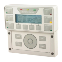
The MATE3s connects to other OutBack products using
the HUB port. To learn what configurations are available,
see the appropriate manual. To make MATE3s settings
for a configuration, see the MATE3s Programming Guide.
FLEXmax
Charge
Controller
(FM80)
M
AT
E
R
T
S
MATE3s
Inverter
PV
+
PV
–
BAT
–
BAT
+
MATE
Port
(RJ45)
RTS
Port
(RJ11)
MATE3s
FLEXmax
Charge Controller
(FM80)
Product
Configurations
(examples)
Communications Interfacing
(examples)
Wi-fi
(no adapter)
Wi-fi
with adapter
Wired
Cellular
Modem
HUB
Port
The MATE3s interfaces with other devices using the Ethernet port.
The connections here are used for Internet access with the OPTICS RE
interface. Other connections are possible. The MATE3s can connect
using a network switch or a wireless network router.
NOTE:
All communications use
CAT5 (non-crossover) cable.
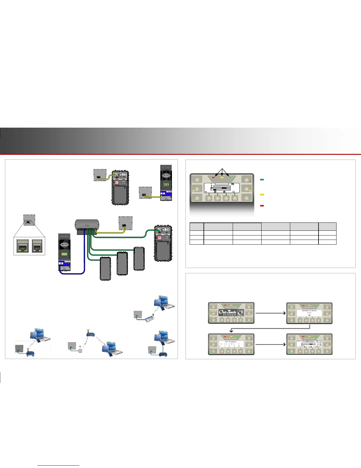
Battery LED Indicators
Three LED indicators indicate the condition of the battery bank.
GREEN means the batteries have an adequate charge at that
time. It does not always mean they are full. If the FLEXnet DC
battery monitor (FN-DC) is installed, this means the batteries are
80% State of Charge (SOC).
Y
ELLOW means the batteries are somewhat discharged. If the
FN-DC is installed, this means the battery SOC is between 60%
and 70%.
R
ED means the batteries are greatly discharged and may require
attention. If the FN-DC is installed, this means the battery SOC
is less than 60%. This indicator may be accompanied by a
Low Battery V error and the EVENTS indicator. (See page 5.)
BATTERY STATUS
INVERTER
GEN
CHARGER
EVENTS
FAVORITE
AC INPUT
1.5
kW
0.1
kW
115
V
1.5
kW
28.5
V
0.00
kW
0.0
kW
G
G
OutBack Power
1.5 kW
1.5 kW
115 V
1.5 kW
85%
28.5 V
System
OK
0.00 kW
0.0 kW
G
G
Battery Status Indicators
NOTES:
Gaps in the table (higher-voltage units) are due to the resolution of the inverter’s DC meter.
These voltage settings are not the same as the inverter’s Low Battery Cut-Out voltage. The Battery LED settings cannot be changed.
Voltages higher than shown in the GREEN row usually means that the batteries are charging.
Displays
Power Up
Device
Identification
Port
Assignment
Home
Screen
When the MATE3s is plugged into a powered OutBack product, it immediately powers up and cycles through
the startup screens. It will proceed to locate and identify the attached components and the ports they occupy
on the HUB. It will then stop on the “Home” screen.
RED 11.4 Vdc or lower 22.8 Vdc or lower 34.2 Vdc or lower 45.6 Vdc or higher Low
YELLOW 11.5 to 12.4 Vdc 23.0 to 24.8 Vdc 34.5 to 37.2 Vdc 46.0 to 49.6 Vdc Usable
GREEN 12.5 Vdc or higher 25.0 Vdc or higher 37.5 Vdc or higher 50.0 Vdc or higher Acceptable
24 Vdc Unit
± 0.2 Vdc
Color 12 Vdc Unit
36 Vdc Unit
± 0.3 Vdc
48 Vdc Unit
± 0.4 Vdc
Battery
Status
Page 2
Communications
900-0124-12-01 Rev A
©2017 OutBack Power Technologies. All Rights Reserved.
Page 3
LED Indicators
 Loading...