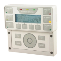
EVENTS indicator (red): An “event” is a change in status, externally imposed on a device
on the HUB (an on/off command, an automatic generator start, loss of grid power, etc.).
The Event History screen logs all events for potential troubleshooting (see page 17).
The LED indicator means that an event requires acknowledgement. Usually it only
illuminates when a fault occurs.
ON (solid): An error has occurred. This is usually accompanied by inverter shutdown.
This can also show a generator fault if the voltage is lost from an automatic generator.
ON (flash): A warning has occurred. It stops flashing if conditions return to normal.
OFF: No particular status. Events may be logged in Event History, but they do not
require attention.
AC INPUT indicator (yellow): This shows the status of the inverter’s AC input
(the master inverter in a stacked system).
ON (solid): The AC source is connected and providing power. Unit may or may not
be charging the batteries, depending on settings.
ON (flash): The source has not been accepted. If this continues, the source may have
quality issues. (See page 10.) The AC Input Status may be set to Drop. (See page 18.)
Also, HBX or a similar function may have disconnected the source. (See the MATE3s
Programming Guide.)
OFF: no AC source is detected.
FAVORITE indicator (green): This indicates the use of this hot key to select
often-used menus for rapid access.
ON (solid): The hot key has been pressed and a Favorite can be selected.
ON (flash): The hot key has been held down to program a Favorite.
OFF: No particular status. The indicator only illuminates upon pressing the hot key.
Meter Bars
Much of the Home screen data is shown by kilowatt meters in the form of black bars next to the various icons.
These meter bars expand to the right or to the left. Not all data is present in all cases. Each home screen uses
a different combination of meter bars. The scale of each bar is described on page 7. The parameters for the
bars are based on the data in System Information.
o The meter bar represents the charge controller output. If no charge controller is detected, this bar is not present.
o The left meter bar represents inverter output when System Type is set to Off Grid or Backup.
o The right meter bar represents the inverter’s charger output when System Type is set to Off Grid or Backup.
o The meter bar represents the generator output when System Type is set to Off Grid.
o The left $ meter bar represents the power bought from the grid when System Type is set to Grid Tied.
o The right $ meter bar represents the amount of power sold by the inverter when System Type is set to Grid Tied.
o The meter bar represents the amount of power used by the output loads when System Type is set to Grid Tied
or Backup.
BATTERY STATUS
INVERTER
GEN
CHARGER
EVENTS
FAVORITE
AC INPUT
OutBack Power
1.5 kW
0.1 kW
115 V
1.5 kW
85%
28.5 V
System
OK
0.00 kW
0.0 kW
G
G
OutBack Power
1.5 kW
1.5 kW
115 V
1.5 kW
85%
28.5 V
System
OK
0.00 kW
0.0 kW
G
G
System LED Indicators
The six System indicators show the status of different aspects of the system.
In most cases, more information is available by pressing the “hot” key where the
indicator is located. Pages 14 through 18 have more information on these hot keys.
INVERTER indicator (green): This shows the status of the inverter
(or the master inverter in a stacked system).
ON (solid): inverter is converting DC power to AC in order to power loads.
ON (flash): inverter is in Search mode.
OFF: the inverter is not converting DC to AC. The AC source may be powering the loads.
CHARGER indicator (yellow): This shows the status of any charger active
in an OutBack system.
ON (solid): a device on the HUB is delivering more than a minimal amount of charging
power. The device may be an inverter or a charge controller.
ON (flash): the batteries are being equalized.
OFF: no device is actively charging the batteries. The charger may be off. It may be on
but in a resting state. Alternately, it may be on with the charging source disconnected or unavailable.
GEN indicator (green): This shows the status of a generator that is controlled by the Advanced Generator Start (AGS) function.
ON (solid): The generator is running after an ON command in the Generator Status menu. The generator is determined to be running
based on input AC voltage (if the generator type is AC). This LED will usually illuminate in conjunction with the AC INPUT LED
indicator. It only illuminates when an AC generator is used.
OFF: The Generator Status menu has been set to OFF, or the AGS function has not been enabled. If the generator shuts down or
stops delivering power, this indicator will remain on until a generator fault is declared.
Home Screen
The Home screen appears after the MATE3s detects the devices connected to it. Home screens display different
types of information depending on the system type selected. This is set in the System Information screen. (See
the MATE3s Programming Guide). Three System Types (and Home screens) are available:
o Off Grid is for when no utility grid is available. Often used with a generator.
Th
is is the default screen.
o Backup is for using the inverter system to back up the utility grid.
o Grid Tied is for grid-interactive inverters capable of returning power to the utility grid.
Most com
monly used with renewable energy
systems.
NOTE:
Selecting Grid Tied does not activate the grid-interactive function.
It simply
arra
nges the screen to display grid-interactive data most effectively. The function
must be set in the inverter itself. FXR- and Radian-class inverters need to be pl
aced
in the AC input
mode which is also called Grid Tied. GTFX and GVFX inverter
s have
this fun
ction enabled by default.) See the applicable inverter literature.
For a legend of the screen
symbols, see page 6.
Page 4
LED Indicators
900-0124-12-01 Rev A
©2017 OutBack Power Technologies. All Rights Reserved.
Page 5
Home Screens
 Loading...