E-122-8-E
1
7.5.5 About Alarm Output (option)
●
When the instantaneous flowrate exceeds (or falls below) a preselected setpoint, the counter lights up a
front-panel LED and, at the same time, produces a remote alarm output (non-contact relay).
●
Alarm comes in Alarm 1 and Alarm 2 which can independently be established.
For parameter menu trees associated with alarms, see "Table 7.5 Menu Trees and Switch
Operation" on page 19.
Parameter Symbol Name Description
A 1 d □□□□□
Alarm 1 setup Sets flowrate at alarm output 1 (in hourly flowrate).
A 1 H □□□□□
Alarm 1 hysteresis
Hysteresis at alarm output 1 (set in hourly flowrate)
… the width or lag from alarm setpoint to alarm cancellation
A 1 S △○
Alarm 1 status
Alarm 1 output status
△: High alarm or low alarm setup
"H" set → high alarm
"L" set → low alarm
○: Remote output at an alarm (non-contact relay)
"S" set → shorted (… contacts "closed")
"O" set → open (… contacts "open")
A 2 d □□□□□
Alarm 2 setup Alarm output 2 flowrate (similar to A1S in meaning)
A 2 H □□□□□
Alarm 2 hysteresis Alarm output 2 hysteresis (similar to A1S in meaning)
A 2 S △○
Alarm 2 status Output status of alarm output 2 (similar to A1S in meaning)
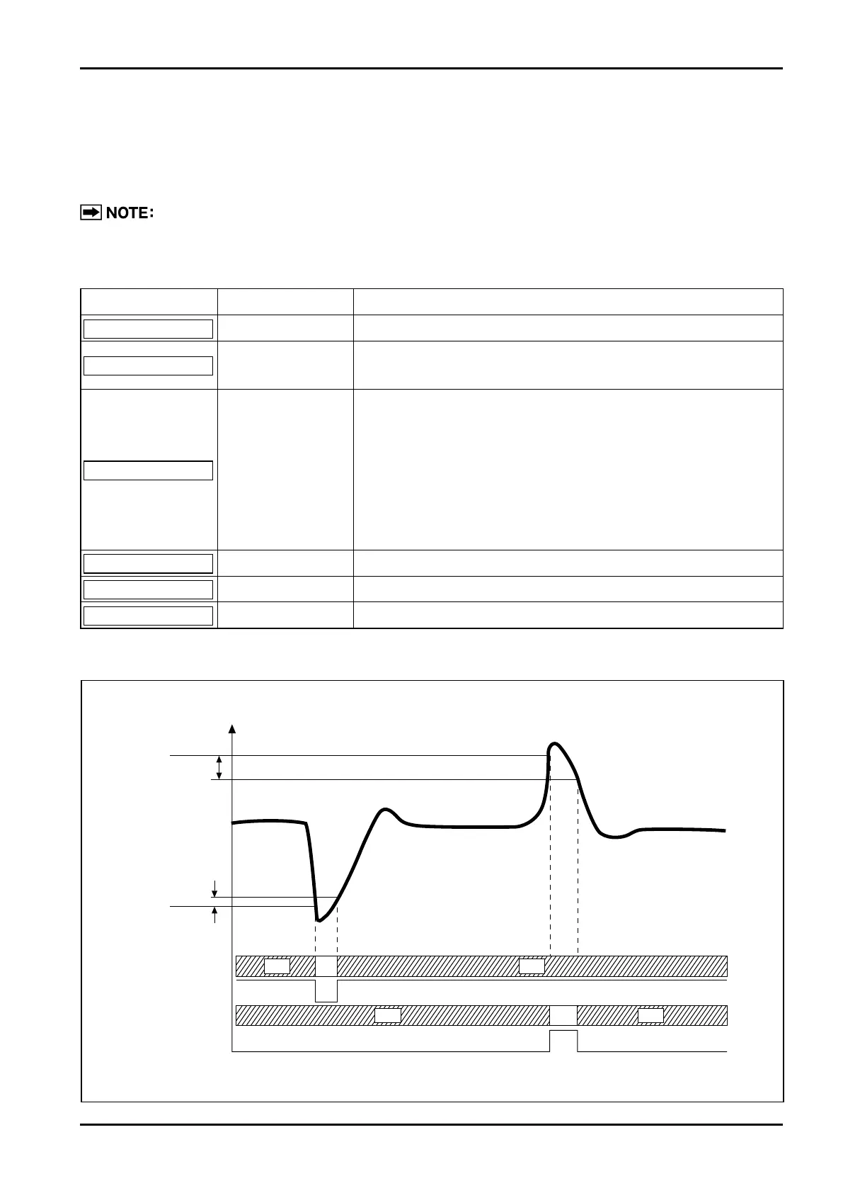
Example: A1d=500, A1H=5, A1S=LS, A2d=1000, A2H=10, A2S=H0
OFF ON
Instant. flowrate
Alarm 1 LED
A2d=1000
A2H=10
A1H=5
A1d=500
O: Open C: Closed
Alarm output 1
Alarm 2 LED
Alarm output 2
C
C CO
O O
OFF
OFFOFF
ON
Table 7.3 Parameters Associated with Alarm Functions and their Meanings