5. WIRING
5.1 Cables for Field Wiring
Use electrostatically-shielded, polyethylene-insulated, vinyl-sheathed control cables (CEVS 0.75 to 2mm
2
,
2- or 3-conductor), or equivalent, for input and output signal cables.
5.3 Terminal Block for External Connections
Before connecting the cables, ensure that the flowmeter (pulse generator) is compatible with this counter.
Acceptable combinations of these units can be determined by identifying their model number and
instrument number.
Invalid equipment combination can lead to a costly downtime. Be sure to reconfirm validity
following wiring connections.
5.2 Field Wiring and Electrical Connections
(1) It is recommended that cables be routed through conduits.
Be sure to route the power cable separate from the input and output signal cables.
(2) Keep the cables away from other power cables or power circuits if any, to prevent stray current pickup.
If inductive interference is suspected, use a capacitor or surge suppressor where necessary.
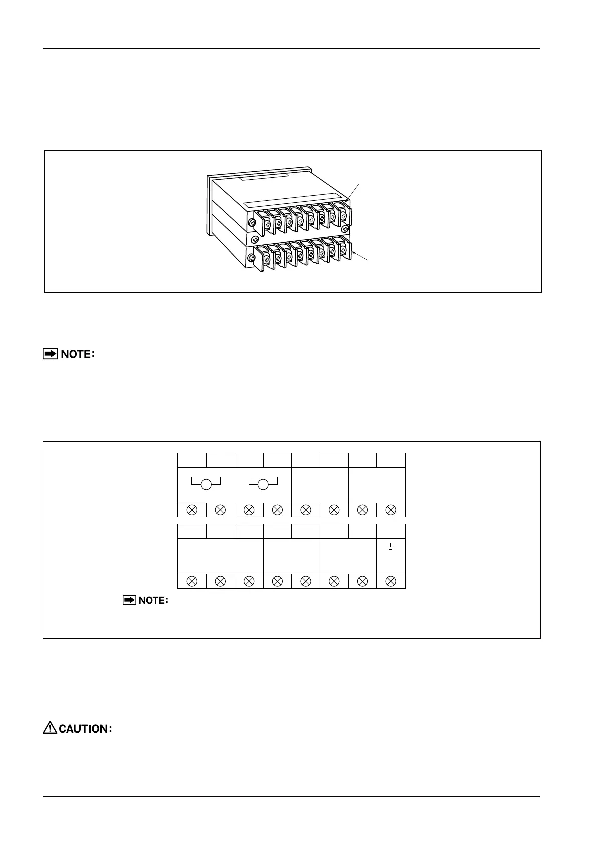
(3) Use crimp-style terminals to ensure good electrical connections. Terminals for connections are located
on the back of this instrument.
Fig.5.2 Extermal Conn. Terminal Blocks
1
A
+
-
+
-
2 3 4 5 6 7 8
V
+
-
ANALOG OUT
ALARM1 OUT ALARM2 OUT
1 2 3 4 5 6 7 8
L1(
+
) ( )L2(
-
)
FLOW INPUT PULSE OUT POWER
SUP SIG. 0V
The upper terminal block at back of the counter is provided only in
models with analog/alarm output.
Terminal block
(Installed in models with analog/alarm output)
Terminal block
Fig.5.1