
R
Randy ReynoldsSep 8, 2025
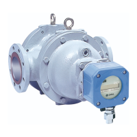
Why are my Oval ULTRA UF-II Measuring Instruments making unusual noises?
- PpruittjohnSep 8, 2025
If you notice unusual noise from your Oval Measuring Instruments, it could be due to a few reasons. Air might be entrapped, so decrease the flow rate and eliminate air in the piping assembly. Alternatively, the metered liquid might be vaporizing, so decrease the flow rate and control the fluid's temperature and pressure to prevent vaporization.


