Installation
5
OWC Data Doubler
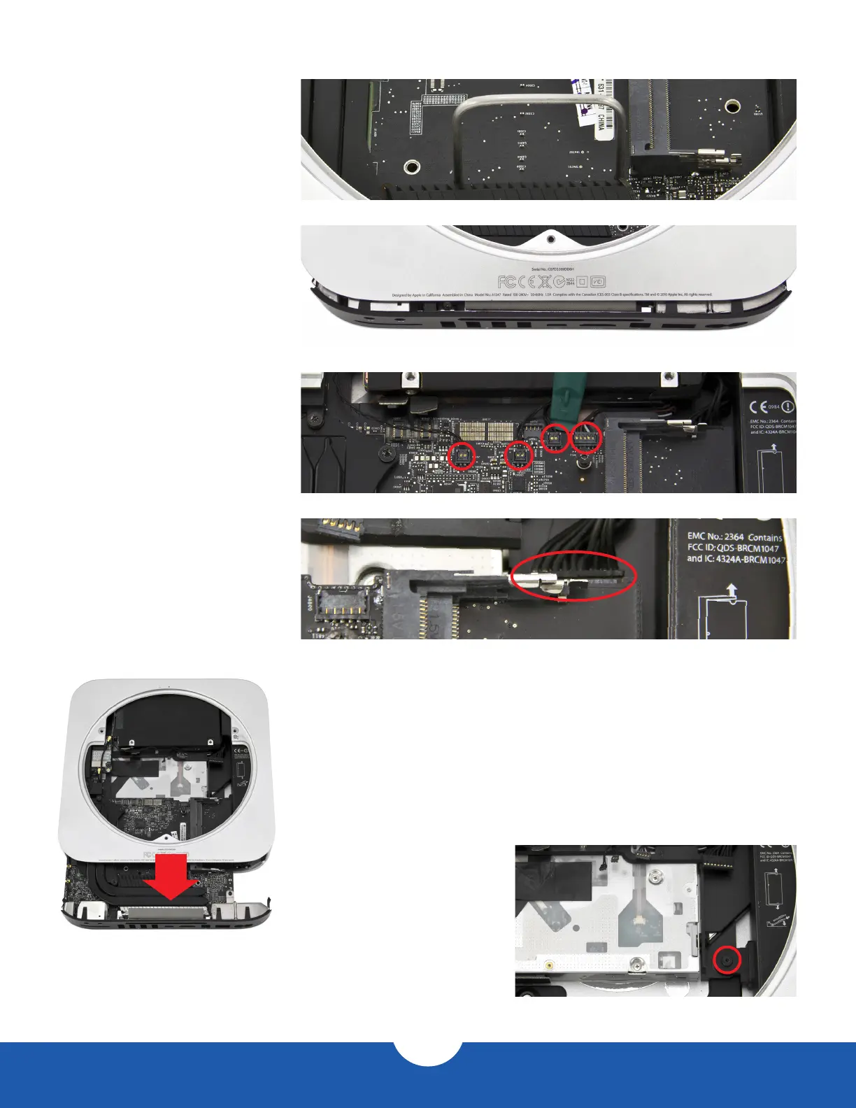
14. Gently push down on the
logic board removal tool and pull
it back until the black plastic
I/O wall pulls away from the
aluminum housing slightly, as
shown in the pictures to the right.
➥
➦
15. Use the nylon pry tool to
disconnect the four cables circled
in the picture to the right. Lift the
cable connectors straight up; do
not pull on the wires.
16. Disconnect the power supply
cable, circled in the picture to the
right. Wiggle out the connector
with either your ngers or the nylon
pry tool. A pair of tweezers may
also help.
17. Now that all the cables are disconnected, slide the logic board
assembly the rest of the way out of the housing, as shown in the
picture to the left. Be careful to keep the logic board assembly
level and avoid catching any of the components on the housing.
Be particularly careful when the memory bracket comes out.
If the bracket is not level, the bracket clip could catch on the EMI
gasket at the top of the housing.
18. To remove the power supply,
rst remove the T6 screw
circled in the picture to the right.