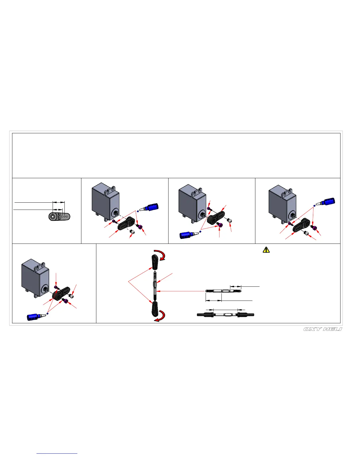
17.50( for Cyclic )
14.50 ( for Tail Servo )
M2x6 Hex Cap Screw
Ref 30.50
14mm
Clock Wire
20mm
Counter Clock Wire
-
You should now do some initial setup of your FBL unit and servos.
- We recommend you select a new model in your transmitter, and reset your FBL unit and start with a clean setup in it as well.
- After binding your transmitter to the receiver system used with the FBL unit, work your way through the FBL setup instructions to the point
you plug in your servos.
- Now set your collective stick in the middle position, and position the servo arms as close to the correct positions you can on each servo
see the following pages for arm orientations on the various servos.
- Next confirm the servos work in the correct direction, then return the collective stick to the center position.
- Now use your FBL unit to trim the servos so the arms are exactly horizontal (see pictures below).
- This procedure varies between units. Carefully label the position of the servos, then proceed with the installation of the servos as shown.
Chapter 14: Servo & Servo Rod Prepareration
Linkage Ball Position
Servo Screw
Servo Screw
Loctite 243
Servo Arm
Linkage Ball
M2x6 Hex Cap Screw
M2x6 Hex
Cap Screw
Servo Arm
Linkage Ball
Servo Screw
Loctite 243
Servo Arm
M2x6 Hex Cap Screw
Servo Screw
Loctite 243
Linkage Ball
Servo Arm
Linkage Ball
It is really important the servo rods screw onto
the linkages the same amount. The Metal Rod
have one side clock wire thread and one side
have counter clock wire thread
Servo Rod Assembly ( 3pcs)
M3x45 Turnbuckle Rod
Plastic
Linkage Ball
Tail Servo
Cylic Front Right Servo
Cylic Front Left Servo
Cylic Rear Servo
page 37