Installation Manual Nova Series
14
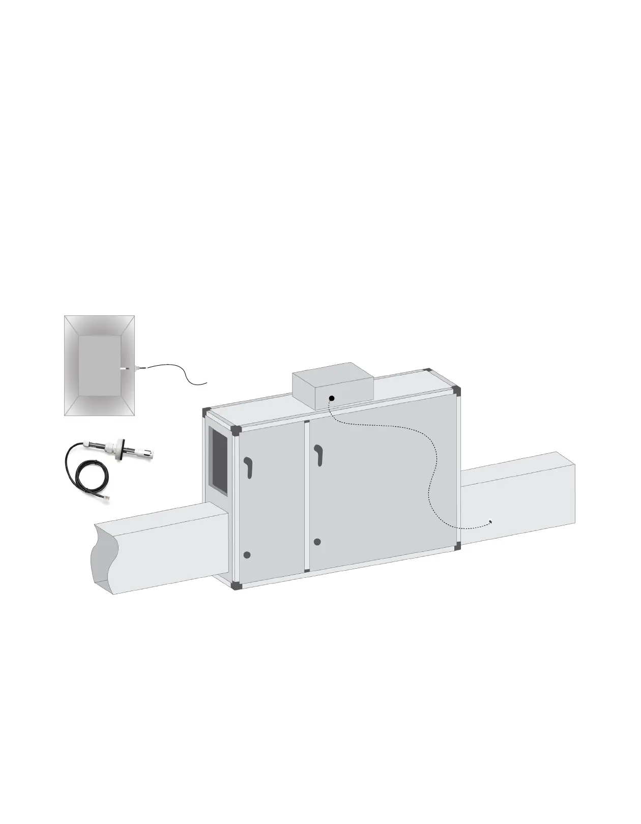
2.7.3 CO/VOC Sensor
VTH-6202 sensors are installed in the ventilation
duct using the accompanying bracket, which must
be attached to a firm, level surface by means of
two screws. The 18-30 V DC supply voltage (24 V
DC nominal voltage) is provided via the Modbus
connection. VTH-6202 has a pre-fitted 7000 mm cable,
which is equipped with a standard RJ12 connector. The
cable may be extended to as much as 50 m without
any negative eects on measuring accuracy. The
surrounding EMC environment must, however, be taken
into account and must be capable of being defined as
low. To extend the cable, use a crossover Category 3
extension cable, RJ12-RJ12, 6P6C. The sensor should
be installed in such a way that the air flow in the duct
can pass unhindered through the measuring hole
at the end of the sensor, which should be aligned
parallel to the air flow. Although the VTH-6202 is not
aected by the position in which it is installed, it should
not be installed in an upright position with the cable
downwards as this may cause moisture to accumulate
in the sensor.
The enclosure is opened without the use of tools
by pressing the snap lock at the side of the tube
connectors. PTH-6202 is attached onto a level
surface by 2 screws, which are screwed into a solid
surface. PTH-6202 can be fitted in all directions
without accuracy being aected. PTH-6202 also
functions with only one tube fitted to the connectors
(+ or -). However, two tubes should always be fitted to
ensure a suitable enclosure rating, if the connectors
do not face downwards. Pressure is supplied to the
measurement unit by tubes, the highest pressure
being connected to the ‘+ connector’ and the lowest
pressure to ‘- connector’. The pressure tubes must be
as short as possible and must be secured in position to
prevent vibration. To obtain the best possible results,
pressure must be measured where there is least risk
of turbulence, i.e. in the center of the ventilation duct
and at a distance of at least twice the width of the duct
from bends and six times the width from branches. If
there is a risk of condensation forming in connection
tubes, PTH-6202 is to be located in such a way that
condensate fluids cannot flow back into the pressure
transmitter.
Supply Air
Return Air
In duct view