Installation Manual Serena Series
7.0 Air Flow Balancing
7.1 Balancing Procedure
It is required to have balanced airflows in an ERV. The volume of air brought in from the outside must equal the volume of air
exhausted by the unit while running at a normal speed. If the airflows are not properly balanced, then:
The ERV may not function at its maximum eciency.
A negative or positive air pressure may occur in the house or condo.
The unit may not defrost properly.
Prior to balancing, ensure that:
1. All of the ERV components are in place and functioning properly.
2. All sealing of the ductwork system has been completed.
3. Set the unit to normal speed.
4. Airflows in branch to specific areas of the house should be adjusted first prior to balancing the unit.
5. After taking a reading of both the stale air to the ERV duct and fresh air to the house duct, the duct with the lower CFM
reading should be left alone while the duct with the higher airflow should be slowed down to match the lower reading by
adjusting the dial/speed controller on the control board.
6. Return the unit to the appropriate fan speed for normal operation.
The following is a method of field balancing an ERV using a Pitot tube in
situations when flow stations are not installed in the ductwork. This procedure
should be performed with the ERV on normal speed.
The first step is to operate all mechanical systems on the most desired speed,
which will have an influence on the ventilation system, i.e. the forced air furnace
or air handler is applicable. This will provide the maximum pressure that the ERV
will need to overcome, and allow for a more accurate balancing of the unit.
Drill a small hole in the duct (about 3/16"), three feet downstream of any
elbows or bends, and one foot upstream of any elbows or bends. These are
recommended distances but the actual installation may limit the amount of
straight duct.
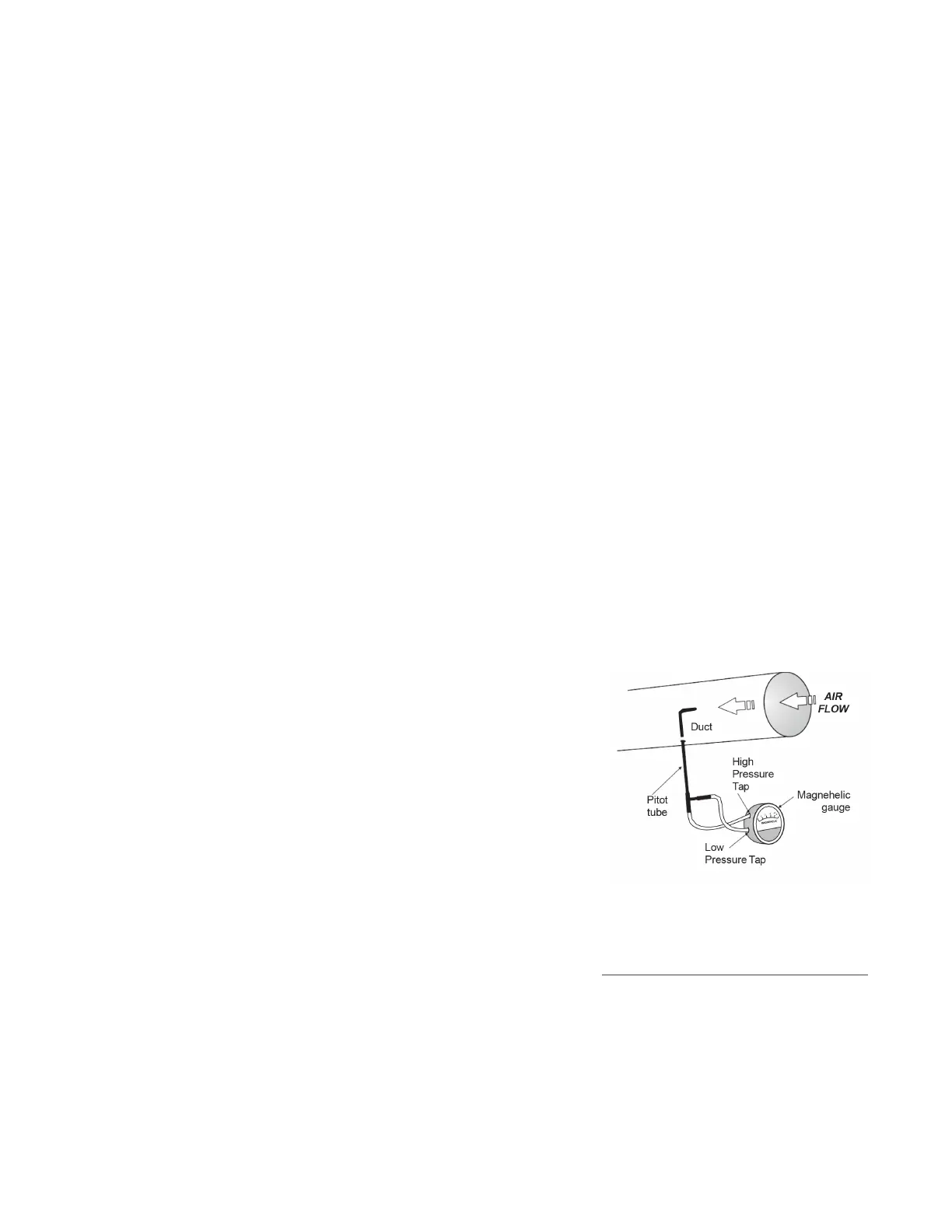
The Pitot tube should be connected to a magnehelic gauge capable of reading
from 0 to 0.25 in. (0-62 Pa) or other digital airflow meter. The tube coming out
of the top of the pitot is connected to the high-pressure side of the gauge/
meter and the tube coming out of the side of the pitot is connected to the low
pressure or reference side of the gauge/meter.
Insert the Pitot tube into the duct, pointing the tip into the airflow. For general
balancing, it is sucient to move the pitot tube around in the duct and take an
average or typical reading. Repeat this procedure in the other duct. Determine
which duct has the highest airflow (highest reading on the gauge), then slow
down that motor speed by adjusting the dial/speed controller on the control
board to match the lower reading from the other duct. The flows should now be
balanced. The actual airflow can be determined from the gauge/meter reading.
The value read on the gauge is called the velocity pressure and on the flow
meter is called the air velocity (FPM). The Pitot tube comes with a chart that will
give the air flow velocity based on the velocity pressure indicated by the gauge.
Note
Place the magnehelic gauge on a level
surface and adjust it to zero.
Pitot Tube and Gauge
7.2 Pitot Tube Airflow Balancing
This velocity will be in either feet for minute
or meters per second. To determine the
actual airflow, the velocity is measured by
the cross sectional area of the duct being
measured.