© 2018 AAMP Global. All rights reserved. PAC is a Power Brand of AAMP Global.
PAC-audio.com
Pacific Accessory Corporation
Page 2
Rev: V5
Date:091218
Advanced Amplier Interface for
General Motors
AP4-GM61
Installation
Be sure to perform the following steps with the ignition off:
1. Access the factory radio module (see location info in Figure 1, next page).
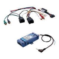
2. Disconnect the Gray 20-pin factory harness and the Gray 8-pin harness from the tuner module (Figure 2, next page).
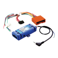
3. Connect the AmpPRO harness to vehicle harness.
4. Connect the AmpPRO harness to factory tuner module.
5. Set any feature DIP switches that apply to your install.
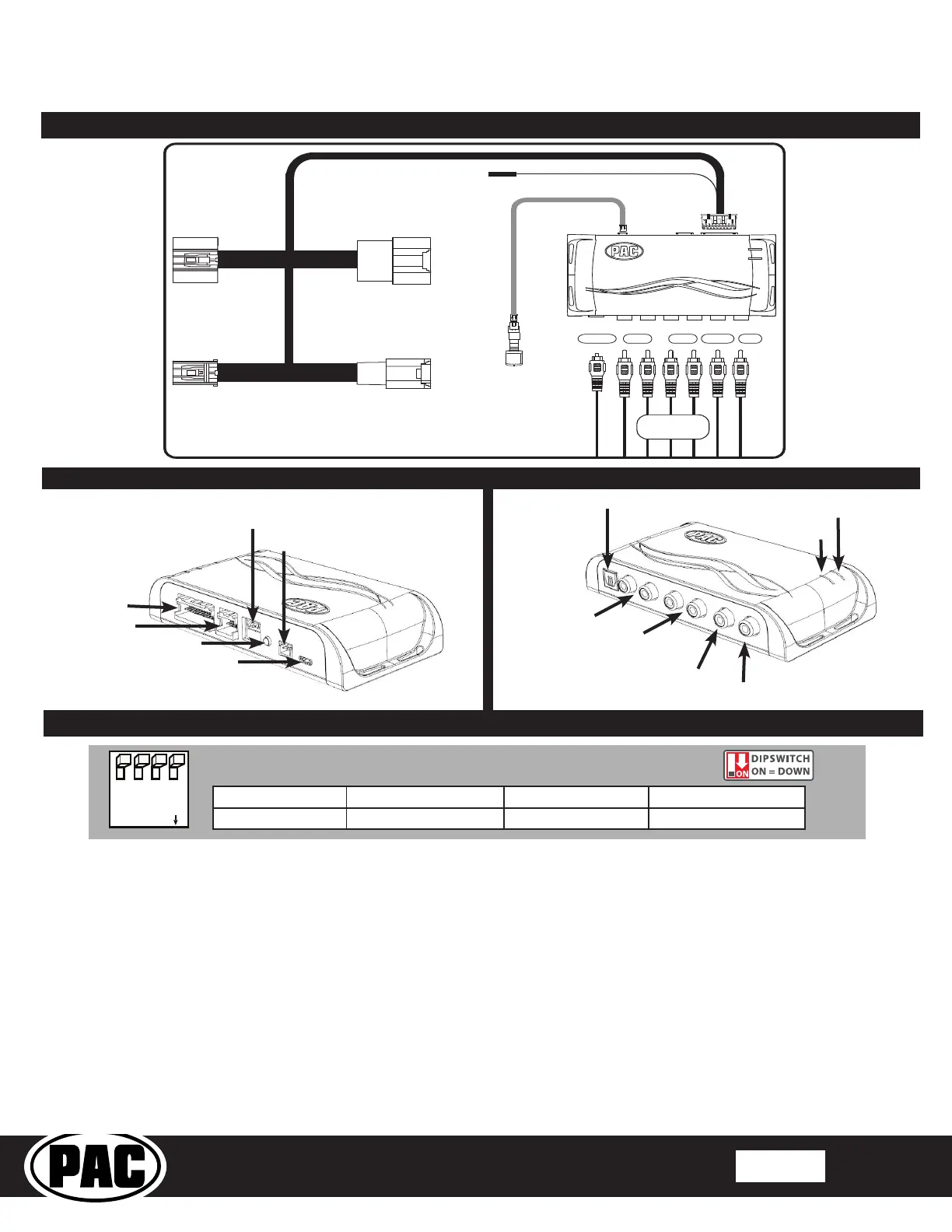
a. DIP switch 1 is used for two channel mode. In this mode, both the TOSLINK and front RCA outputs (1 and 2) become
non-fading outputs. All rear chimes will also be routed through these outputs in two channel mode.
b. Set DIP switch 2 on (down) to lower the RCA output voltage to 4v. Leave DIP switch 2 off (up) to keep the RCA output
voltage at 5v. See the troubleshooting section on page 5 for more details.
6. Connect the AmpPRO harness to the module.
7. Connect the level control knob to the module and install in an accessible location.
8. Connect the signal cables and remote input from the aftermarket amplier.
9. Shut all doors and lock the vehicle with the factory keyfob. Allow the vehicle 5 minutes to go to "sleep".
10. Proceed with setup and conguration.
Two Channel Mode 5v / 4v Preout No Function No Function
1 2 3 4
Set DIP switches to the ON position to activate the corresponding features.
Set DIP switches to the OFF position for any features that are not desired.
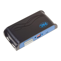
Module Layout
Interface Connector 1
Expansion Port
Programming Button
Feature Select
DIP switches
Non-Fading Level Control
Knob Connection
USB Connection
LED 1
TOSLINK Output
Front Output
Ch. 1(L) and 2(R)
Rear Output
Ch. 3(L) and 4(R)
Non-Fading
Output Ch. 6
LED 2
Center Channel
Output Ch. 5
Wiring Connection Chart
*Non-Fading
Front
1(L) 2(R)
4(R)
5 6
3(L)
Remote Turn On Output
2A Max Output
Rear
5-Center
6-NF*
TOSLINK
Optional
AP4-GM61-HAR
To Tuner
To Vehicle
Harness
Non-Fading
Level Control
Knob
To Aftermarket
Amplifier