GM1A-RST
Radio Replacement Interface with
Steering Wheel Control and Telematics Retention
for select General Motors Vehicles
with Class II Data-Bus
© 2018 AAMP Global. All rights reserved. PAC is a Power Brand of AAMP Global.
PAC-audio.com
Pacific Accessory Corporation
Rev: V6
Date: 100318
Page 2
Installation Steps
Other =
Advent, BOYO, Dual, Lightning Audio, Rockford Fosgate, Visteon
Alpine JVC
Kenwood /
Lightning Audio
Clarion /
Nakamichi
2-Wire
Resistive
Pioneer /
Other*
Sony Fusion
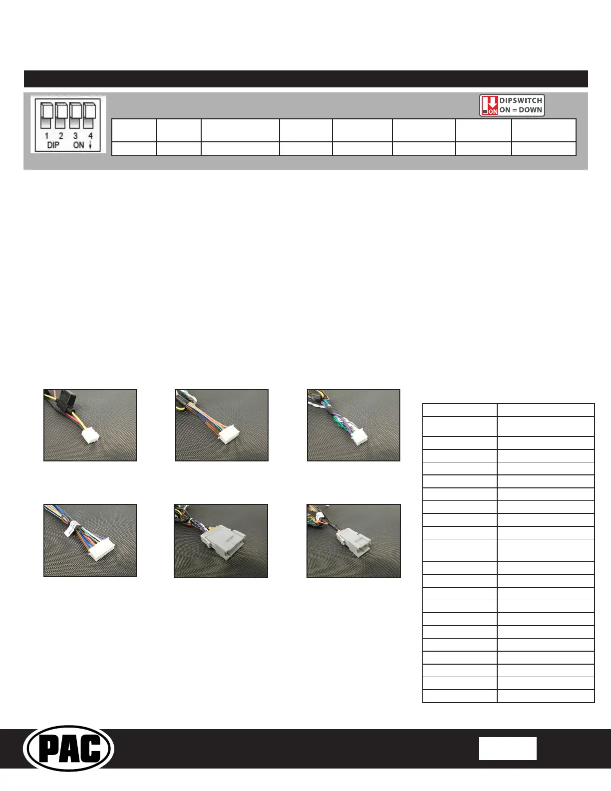
1 2 1 & 2 3 2 & 3 1, 2, & 3 4 1 & 4
Set DIP switches that correspond with your radio to the ON position.
Set all other DIP switches to the OFF position.
*Other - Dual / Axxera (these brands could also have 2-wire resistive), Jensen, Rockford Fosgate
1. Set the Radio Select DIP switches according to the radio you are installing.
2. Wire your aftermarket radio to the GM1A-RST’s harness according to the wiring connections chart below.
3. The Brown mute loop in Interface Connector 4 (if not cut) will turn the GM1A’s accessory output off when any OnStar
function is active. If the aftermarket radio has a mute input, cut this loop and connect the Brown wire in pin 23 to it.
4. Plug Interface Connectors 1 and 2 into the appropriate ports on the GM1A-RST interface (using the diagram on page 1 or
the label on the bottom of the interface).
5. The Connector 3 connection will be dependent upon whether or not the vehicle has a factory amplied system. Plug this
connector into the appropriate port on the GM1A-RST (using the diagram on page 1 or the label on the bottom of the
interface).
6. If the aftermarket radio is equipped with an auxiliary input and you wish to retain the factory RSE audio, plug the RCA
connectors from the secondary harness into the radios auxiliary input.
7. Remove the factory radio and plug in the GM1A-RST’s Vehicle Connector 1 and Vehicle Connector 2 into the factory vehicle
harness.
8. If you wish to reassign functions to the SWC, follow the programming instructions on Page 4.
9. If you are connecting an aftermarket amplier to the cabin speakers, connect the chime speaker to the chime plug coming out
of Interface Connector 4 and install the chime speaker in a place free of obstructions, where it can be easily heard (usually
low in the dash facing downward).
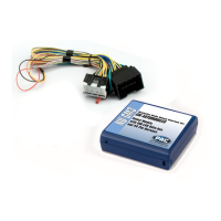
Interface Connector 1
(3-pin)
Interface Connector 2
(20-pin)
Interface Connector 4
(24-pin)
Interface Connector 3
(12-pin)
Vehicle Connector 1
(24-pin)
Vehicle Connector 2
(12-pin)
Yellow 12v+
Red
Accessory Output
(10 amp)
Black Ground
Brown Loop Mute Output
Blue Not Used
Blue / White Remote On Input
Orange Not Used
Orange / White Illumination Output
Purple / White Reverse Output (+)
Light Green Parking Brake Output (-)
Pink Vehicle Speed Signal
(VSS) Output
Blue / Yellow SWC Output / Key 1
Brown SWC Output / Key 2
3.5 mm Jack SWC Output
Purple Rear R + input
Purple / Black Rear R - input
Green Rear L + input
Green / Black Rear L - input
Gray Front R + input
Gray / Black Front R - input
White Front L + input
White / Black Front L - input
Wiring Connections
 Loading...