5
THEORY OF OPERATION
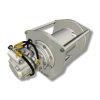
DESCRIPTION OF HOIST
The hoist has four basic component parts:
1. Hoist base
2. Hydraulic motor and brake valve
3. Brake cylinder and motor support
4. Drum assembly
The drum assembly consists of three basic assemblies:
1. Drum with integral ring gear
2. Output planetary gear set
3. Primary planetary gear set
The hydraulic motor is bolted to the motor support which in
turn is bolted to the brake cylinder and the base. The motor
end of the drum, running on a ball bearing, is supported
by the brake cylinder. The other end of the drum runs on
a ball bearing on the support bolted to the base. The ring
gear for both planetary sets is machined into the drum’s
inside surface.
HOIST OPERATION
The hydraulic motor drives the sun gear of the primary
planetary gear set through the splined inner race of the
overrunning brake clutch. When driven by the sun gear,
the primary planet gears walk around the ring gear in the
drum and drive the primary planet carrier.
The primary planet carrier drives the output planet sun
gear which, in turn drives the output planet gears. The
output planet carrier is splined to the bearing support and
cannot rotate. Therefore, as the output planet gears are
driven by the sun gear, they will drive the ring gear/drum.
DUAL BRAKE SYSTEM - DESCRIPTION
The dual brake system consists of a dynamic brake
system and a static brake system.
The dynamic brake system has two operating components:
1. Brake valve assembly
2. Hydraulic motor
The brake valve functions as a counterbalance valve,
but delivers ne load control by eectively metering ow.
It contains a check valve to allow free ow of oil to the
motor in the hoisting direction and a pilot operated, spring-
loaded spool valve, which blocks the ow of oil out of the
motor when the control valve is placed in neutral. When
the control valve is placed in the lowering position, the
spool valve remains closed until sucient pilot pressure
is applied to the end of the spool to shift it against spring
pressure and open a passage. After the spool begins to
open at 300-500 psi (20.7-34.5 bar) cracking pressure the
pilot pressure becomes ow-dependent and modulates
the spool valve opening which controls the lowering
speed. Refer to gures 1, 2, and 3.
The static brake system has three operating components:
1. Spring Applied, Multiple Friction Disc Static Brake
2. Overrunning Brake Clutch Assembly
3. Hydraulic Piston and Cylinder
 Loading...