7
HOIST INSTALLATION
1. The hoist should be mounted with the centerline of the
drum in a horizontal position. The mounting plane of
the base may be rotated in any position around this
centerline.
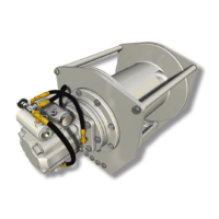
2. Because of the design of the mounting base, the
direction of line pull should only be as shown in the
above illustration. Line pulls in any other direction must
be approved by BRADEN Engineering.
3. When mounting the hoist, use all eight (8) mounting
holes and grade 8 capscrews and nuts. Tighten to
recommended torque.
The hoist must be mounted on a surface which will not
ex when in use, and cause binding of the gear train.
Binding in the gear train will result in accelerated wear
and heat. Also, be sure the hoist is mounted on a at
surface. If necessary, use shim stock to ensure the
mounting surface is at within 0.020 in. (0.5 mm). Use
stainless steel shim stock as required.
4. The vent plug must always be located above the
horizontal centerline. If the hoist is mounted on a
pivoting surface, be sure vent plug remains above
the centerline in all positions. If necessary, reposition
bearing support and vent plug as follows:
A. Remove bearing support bolts.
B. Rotate bearing support until vent plug is positioned
correctly and bolt holes are aligned.
C. Evenly tighten bolts to recommended torque.
5. Hydraulic lines and components operating the hoist
must be of sucient size to assure minimum back-
pressure at the hoist motor ports. The hydraulic back-
pressure measured at the motor work ports must not
exceed 100 PSI (6.9 bar) at full operating ow. Back-
pressure in excess of 100 PSI (6.9 bar) will shorten
motor shaft seal life and partially release the load
holding brake. The standard hoist is supplied with
the gear motor internally drained and connected the
drain by-pass port on the BRADEN brake valve. If high
back-pressures are encountered, the motor should
be externally drained directly to the reservoir and the
“DRAIN” port on the brake valve capped. All piston
motors MUST be drained directly to the reservoir. The
piston motor case drain port must NEVER be exposed
to more than 42 PSI (2.9 bar); shaft seal damage will
occur.
6. The hoist should be mounted perpendicular to an
imaginary line from the center of the drum to the rst
sheave to ensure even spooling. Make certain the eet
angle does not exceed 1-1/2 degrees.
 Loading...