Do you have a question about the Pace ST 45 and is the answer not in the manual?
Overview of the ST 45/ST 55 soldering systems and the provided manual.
Technical details including power requirements, temperature ranges, and EOS/ESD specifications.
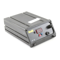
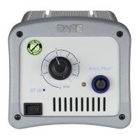
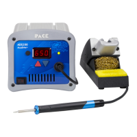
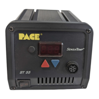
Visual guide to identify system components and their locations on the ST 45 model.
Essential safety precautions for operating and servicing the product, covering shock hazards, burns, and chemical use.
Instructions for positioning the system on a workbench or shelf for optimal use and space conservation.
Guidance on attaching the Tip & Tool Stand to the power source for convenient handpiece storage.
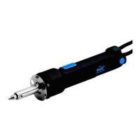
Steps for properly connecting the handpiece to the power source, including alignment and locking.
Procedures for connecting the system to AC power and initial startup, emphasizing proper grounding.
Steps to perform the initial heater burn-in cycle for new handpieces to ensure optimal performance.
Instructions for installing soldering tips into the handpiece heater assembly for proper fit and heat transfer.
Definition of the safety feature that powers down the system after a period of inactivity.
Definition of the standard operating mode where the current tip temperature is displayed.
Definition of the mode for adjusting system parameters like temperature limits and passwords.
Definition of the security feature to prevent unauthorized parameter changes.
Step-by-step guide for rapid system setup and initial use for standard soldering operations.
Explanation of the LED display indicators during standard system operation.
Explanation of the LED display indicators when adjusting the desired tip temperature.
Description of the feature that automatically reduces tip temperature after a period of inactivity.
Explanation of the automatic power-off feature that turns off the handpiece after setback.
Steps to access the system's customization settings via the LED display menu.
Procedure for setting up, changing, or removing a system password for security.
How to set the default temperature display to Celsius (°C) or Fahrenheit (°F).
How to adjust the upper and lower temperature limits for the soldering system.
Procedure for entering tip offset constants for accurate tip temperature readings.
How to configure the automatic temperature setback feature and its time-out period.
How to enable or disable the automatic power-off feature and adjust its time-out period.
How to enable or disable the TDI mode for stabilizing temperature display readings.
Instructions on how to exit the system's set-up configuration and return to normal operation.
Overview of default system configurations for features like password, temperature scale, and limits.
Information regarding system accuracy and calibration requirements, noting no adjustments are necessary.
Descriptions of error messages displayed on the LED screen and their meanings.
Troubleshooting steps for common power source malfunctions, including fuse checks.
Troubleshooting procedures for handpiece-related issues like not heating or overheating.
Detailed steps for replacing the heater assembly on PS-70/PS-90 handpieces for optimal performance.
List of items included with the ST 45/ST 55 soldering systems, specifying quantities.
List of available spare parts for the soldering systems with PACE part numbers.
Information on how to obtain service and repair for the soldering equipment.
Details of the product's one-year warranty coverage, limitations, and exclusions.
| Brand | Pace |
|---|---|
| Model | ST 45 |
| Category | Soldering Gun |
| Language | English |