Do you have a question about the Pace ST 115 and is the answer not in the manual?
Welcome message and overview of the manual's purpose for the ST 115 system.
Technical details and compliance information for the ST 115 system.
Details on voltage and power consumption for ST 115 and ST115E models.
Range and stability of tip temperatures for the ST 115 system.
Measurements and specifications for vacuum rise time, vacuum, pressure, and air flow.
Electrical specifications related to Electrostatic Discharge (ESD) and safety compliance.
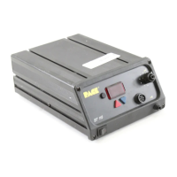
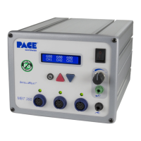
Labeled diagram identifying key components and ports of the ST 115 unit.
Essential safety precautions for operating and servicing PACE products.
Instructions for attaching and using the Tip & Tool Stand with the ST 115 system.
Procedures for connecting air hoses and preparing the VisiFilter for handpieces.
Steps to connect the handpiece connector plug to the power source.
Instructions for connecting the power cord and powering on the ST 115 system.
Procedure to ensure optimum performance and longevity of new handpiece heaters.
Overview of the ST 115 system's ease of operation and quick setup.
Step-by-step guide to quickly set up and begin operating the ST 115 system.
Explanation of key terms used in ST 115 system operation procedures.
How to activate, enter, and manage the password feature for system security.
Feature to set and display true tip temperatures for various handpieces and tips.
Describes the LED display indicators during normal system operation.
Explains LED display indicators when adjusting set tip temperature.
How the system automatically lowers tip temperature to preserve tip life and save energy.
Methods to exit the Temperature Setback mode and return to normal operation.
Safety feature that removes power after a period of inactivity following Temperature Setback.
Procedures to exit the Auto Off mode and resume normal system operation.
A guided walkthrough of the ST 115 system's features and basic adjustments.
Overview of default system features and their factory-assigned settings.
Explains how to customize the ST 115 system using the Set-Up Mode.
Step-by-step instructions to access the system's Set-Up Mode.
Procedures for managing passwords within the ST 115 system's Set-Up Mode.
How to set the default temperature scale (°C or °F) in Set-Up Mode.
Instructions for changing the upper and lower temperature limits in Set-Up Mode.
Setting the Tip Offset Constant for accurate temperature compensation.
Adjusting the timeout period for the Temperature Setback feature.
Configuring the Auto Off feature and its time-out period.
Enabling or disabling the Temperature Display Impedance mode.
Procedures to exit the Set-Up Mode and return to normal operation.
Steps for diagnosing and correcting malfunctions in the ST 115 system.
Information on maintaining the accuracy of the system's LED display.
Explanation of error messages displayed on the LED screen and their meanings.
A guide to resolving minor malfunctions based on symptoms and solutions.
Troubleshooting procedures for handpiece heater assembly checkout.
Step-by-step instructions for disassembling and assembling the ST 115 power source.
Labeled diagram showing the major internal components of the ST 115 power source.
Electrical wiring schematic for the ST 115 system.
Detailed electronic schematic of the ST 115 system's circuitry.
List of items included with the ST 115 system shipment.
Catalog of available spare parts for the ST 115 system.
| Brand | Pace |
|---|---|
| Model | ST 115 |
| Category | Soldering Gun |
| Language | English |