Do you have a question about the Pace SX-100 and is the answer not in the manual?
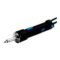
The PACE Sodr-X-Tractor Handpiece is a specialized tool designed for thermally enhanced through-hole desoldering, particularly effective on extra heavy multilayer assemblies. It operates at safer, lower temperatures, even during continuous use, making it a valuable tool for delicate rework.
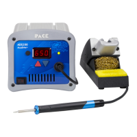
The Sodr-X-Tractor handpiece facilitates the removal of solder from through-hole components. It utilizes a vacuum system to extract molten solder, ensuring a clean and efficient desoldering process. The handpiece is available in two main models: SX-80 and SX-90. The SX-80 features yellow coloration and is exclusively available with SensaTemp technology. The SX-90, with blue coloration, is available in both SensaTemp and Intelliheat technologies. The device is part of the PACE SensaTemp family of advanced handpieces, known for their thermal performance and control.
The handpiece connects to a PACE power source via a connector plug. It requires a vacuum hose connection, which involves attaching a 137cm (54 inch) length of air hose to the metal tube at the back of the handpiece. For systems with multiple air handpieces, additional quick connect hose mount fittings are recommended for ease of switching. A crucial component is the VisiFilter element, which must be kept clean to prevent performance deterioration or damage to the unit.
The Sodr-X-Tractor uses specific tips for desoldering. PACE Endura Tips come in three types: Desoldering Tips (tinnable, enhanced thermal performance), Precision Tips (smaller ID, larger mass for improved thermal recovery), and Flo-D-Sodr Tips (rapid, continuous extraction of solder from SMT lands). Tip selection is critical; for through-hole desoldering, the tip's inner diameter (ID) should be just large enough for the lead to pass freely, and the outer diameter (OD) should not exceed the land diameter to prevent board substrate damage. SX-70 tips are not compatible with SX-80 or SX-90 handpieces. SX-80 (Endura) tips work with SX-70, SX-80, and SX-90 handpieces. SX-90 tips are only compatible with SX-90 handpieces. For optimal thermal transfer and performance, SX-90 tips should always be used with SX-90 handpieces and heater assemblies.
The heater assembly is a modular design, allowing for quick and easy replacement. There are two heater options: a black plug-in connector (part number 6010-0107-P1) and a blue plug-in connector (part number 6010-0163-P1). These are not interchangeable.
The handpiece features a slim-line, pencil grip design and a finger-actuated vacuum switch, enhancing ease of use and manipulation in tight spaces. It also includes a large, easy-to-replace solder trap.
For tip installation, tips should be inserted fully into the heater bore using the supplied tip tool (P/N 1100-0206), and the Heater Set Screw should be gently tightened and periodically rechecked. It is recommended to install tips when the heater is hot.
Temperature setting is crucial for optimal results and to prevent damage to the PCB. PACE recommends using the lowest possible tip temperature that provides rapid and controllable melt of the solder joint. A starting operating temperature of 316°C (600°F) is suggested, with adjustments as necessary. Temperatures exceeding 399°C (750°F) may cause damage. For heavy assemblies, preheating or auxiliary heating may be required for safer removal.
A "Burn In" procedure is required for optimum performance and product life. This involves setting the handpiece tip temperature to 316°C (600°F) for 10 minutes, then to 427°C (800°F) until smoke emission ceases (approximately 15 minutes). This should be done in a well-ventilated area.
Proper tip preparation is essential before each component removal or land preparation operation and prior to storage. This involves cleaning the tip with a moistened sponge to remove solder dross and flux residue, then tinning the end of the tip with large gauge, flux-cored wire solder to enhance heat transfer and extend tip life.
During through-hole solder extraction, the handpiece vacuum hose must be connected to a VisiFilter and the Vacuum Port on the power source. The extractor tip should be gently positioned over the lead, perpendicular to the pad and board, without applying pressure. The lead should be moved in a circular motion for round leads or back and forth for flat leads until it moves freely, indicating complete solder melt. Vacuum should then be actuated for at least 2 seconds to cool the joint and prevent re-sweating. Early vacuum activation may lead to incomplete solder removal. After removing the tip from the pad, vacuum application should continue for an additional 2 seconds to ensure all residual solder is drawn into the collection chamber. The tip should then be re-tinned and returned to its Tool Stand. If solder remains in the plated thru-hole, the connection should be resoldered and the procedure repeated.
The Sodr-X-Tractor requires minimal special maintenance beyond keeping it clean. The heater bore should be periodically cleaned with a 3/16" O.D. wire brush (P/N 1127-0014-P5) to ensure optimum heat transfer and proper tip grounding. The heater bore and the heater assembly set screw, which secures the tip, must be kept free of oxidation and debris to maintain proper tip-to-ground resistance.
The disposable solder collection trap needs regular replacement. This involves pulling the plunger assembly from the handpiece, removing the solder assembly, and then pulling the plunger approximately 10 degrees to the right or left to remove the door assembly. The disposable chamber is then removed by pulling the door assembly near the ear-shaped protrusions and lifting straight up. A new disposable chamber is inserted, ensuring the directional arrows on the solder chamber are pointed at the heater. The plunger assembly is reassembled by lowering the door into the handle assembly, inserting the door properly, and twisting the plunger locks mechanism.
Heater replacement is straightforward due to the modular design. The installed tip is removed, the handpiece is disconnected from the power source, and two heater assembly screws are removed from the face of the heater shroud. The heater assembly is then pulled straight out. Reassembly involves aligning the modular heater plug with the receptacle on the handle assembly, gently pushing it into place, and replacing the two heater assembly screws, ensuring the heater assembly is snugly in place without overtightening.
| Brand | Pace |
|---|---|
| Model | SX-100 |
| Category | Soldering Gun |
| Language | English |