8
SINC 250314-24
Full Flue Liner - (Required in Canada)
1) Measure the chimney height from the top of the existing
ue to the oor of the hearth. This will allow extra length
of liner for ashing and rain cap.
2) Feed the stainless steel liner from top of the chimney,
through the damper area and into the replace cavity.
Attach a stove connector to the bottom of the liner.
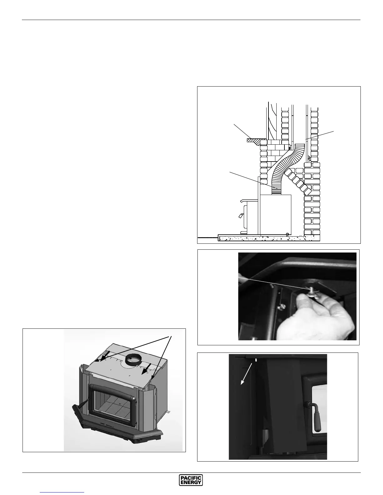
3) Remove bay top and both right & left blower covers
(Fig #4 & 6).
4) Remove casing top by removing screws on each casing
side and pulling top forward(Fig. #5).
5) Push insert into replace. Use the rear adjustment legs to
level insert. (NOTE: Adjustment legs are located in bottom
rear of insert)
6) Measure, trim and shape a top ashing to t the existing
chimney ue. Plan for a 1” to 1-1/2” overlap on each side.
Place ashing over top of the liner and seat rmly against
the tile.
7) Caulk around liner with high temp stove cement and insert
into collar. Screw in fasteners to secure.
8) Attach a rain cap to the end of the liner. A storm collar
may be used if desired.
9) Reattach casing top with screws previously removed.
Consult your local Dealer about relining your replace
chimney.
Direct Flue Connection (USA only)
1) Measure from the rst chimney ue liner tile to the top of
the Insert. Allow extra length of liner to insert into ue
tile.
2) Feed the stainless steel liner through the damper area
and into the rst chimney ue tile. Seal around pipe.
Note: A clean-out door may be required under local codes,
when a direct ue connection is used. Consult local codes.
3) Remove bay top and both right & left blower covers
(Fig #4 & 6).
4) Remove casing top by removing screws on side and pull-
ing top forward(Fig. #5).
5) Push insert into replace. Use the rear adjustment legs
to level insert.
6) Attach connector pipe to stove collar.
7) Reattach casing top and fasten.
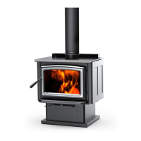
Chimney
Flue Liner
Fig. # 5
6" Stainless Steel
Rigid or Flex Liner
Mantel or
Top Facing
Direct Flue Connection
Fig. # 3
Fig. # 4
Fig. #6
SCREWS
“Wing” Screw