10
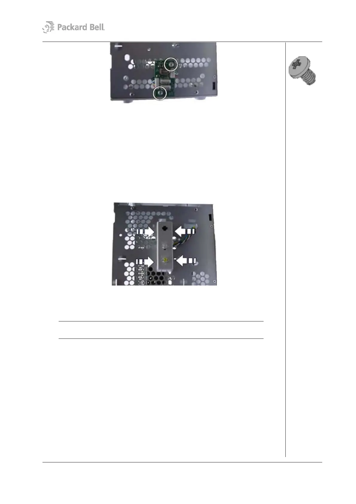
Fig. 14: Removing the front USB port screws
Removing the Switch/LED Assembly
To remove the switch/LED assembly and the cable, first remove the rear bezel (see section
Removing the Rear Bezel) and remove the left side cover (see section Removing the Left
Side Cover), remove the front bezel (see section Removing the Front Bezel); then follow
the steps below:
1. Disconnect the cable from the motherboard.
2. Unlock the housing by applying pressure on the latches on both sides of the
switch/LED assembly.
Fig. 15: Removing the switch/LED assembly
3. Gently pull away the cable and the switch/LED assembly from the chassis.
Note: When reassembling the switch/LED assembly, take care that you return it to
its original position, i.e. with the switch at the top and the LEDs at the bottom.
Removing the CPU
To remove the CPU, first remove the rear bezel (see section Removing the Rear Bezel)
and remove the side cover (see section Removing the Left Side Cover); then follow the
steps below:
1. Disconnect CPU fan cable connected to the motherboard.
2. Remove the CPU fan and heat sink by pressing the metal clip on both sides of the
heat sink until unlocks.
Packard Bell Stella (iXtreme) Disassembly Manual