ILK 22/33/44/55/66 INSTALLATION MANUAL
Revision 1.6 - 32 -
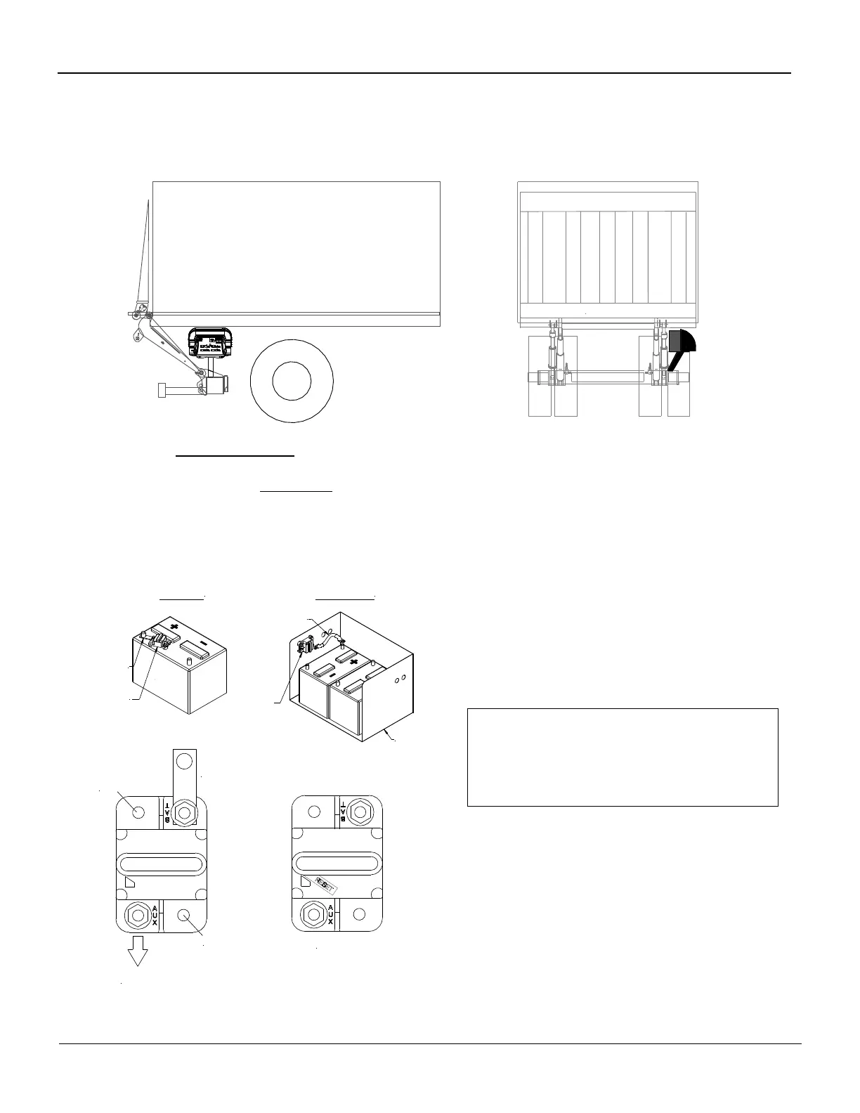
Breaker Installation (Fig. 6.1)
1. Determine location for fixed control box; locate it in a way that the operator can view the platform
and surrounding areas while operating the liftgate. Also, locate in a way where the lid does not ex-
tend outside the van body when open.
2. Lead the 4-wire cab switch together with the battery cable and the 4 wires for the control power to
the batteries along the sub-wood. Secure the cable every 12 inches against the sub-wood with cable
staples. Run only the cab switch into the cab. Battery cable and 4 wire control power cable will go di-
rectly to the truck battery. (#2 and #4 go to positive post with an inline 20 amp fuse; #1 and
green/yellow go to negative post)
3. Install the supplied breaker to the positive terminal of the battery using copper buss ban.
4. Mount circuit breaker securely on top of battery
5. Connect 2Ga. Cable from liftgate to the circuit breaker
 Loading...