ILK 22/33/44/55/66 INSTALLATION MANUAL
Revision 1.6 - 33 -
Always connect 4 wire harnesses directly to Truck/Trailer Battery.
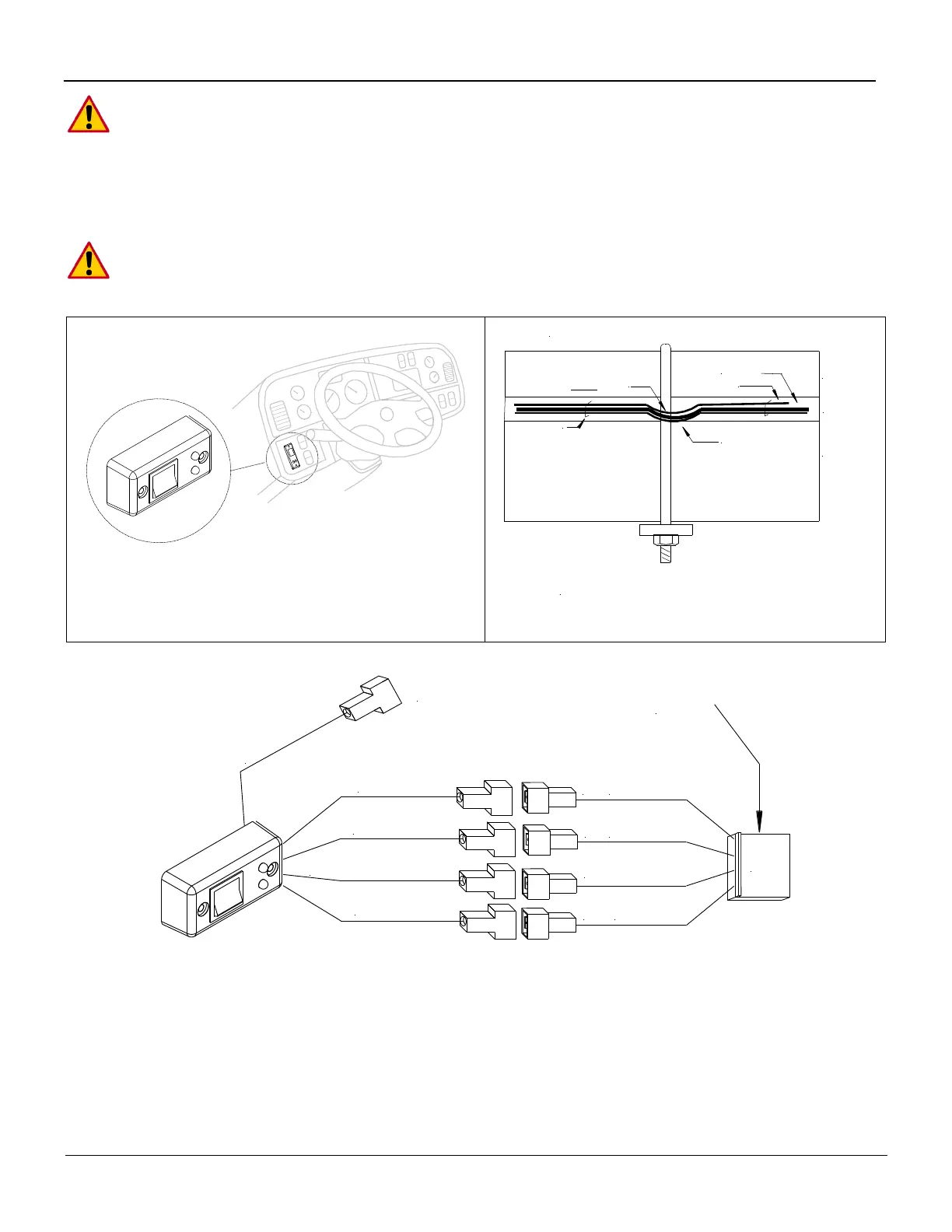
On-Off Switch Installation Truck Application (In Cab)
Install the cab shut-off switch inside the cab. Locate it where it can conveniently be seen and reached from
the driver’s seat as well as from the ground.
Do Not use In-Cab Switch for Trailer Applications. Your Liftgate should be outfitted with a
trailer shut-off Switch and wiring in control box from the factory. If not, refer to “Cut Off
Switch for Trailer Application” 6.2.
Place cab shut off in view of the driver and within reach
from the ground.
Recommended Cable Routing for Trucks
Body Stringer
Sub Wood
Truck Frame
Cable Staples
Route Cables to
OUTSIDE
of U-Bolts
For trailer installation refer to trailer
manufacturers recommended routing
Battery Cable
2 Wire Control Box Power Cable
4-Wire Control Cable
No Use
Blue #4
Black
Black
(-)Yellow/Green
Yellow/Green (-)
#2
#4
#1
Red #2
J11
Black
Blue (3)
White #1
J11 From
Control
Board
In-Cab Switch Color and Number Coding
Cab Cut off Switch Code Cable wires are marked:
WHITE 1 = Hot Lead To Red L.E.D. Lights -
GREEN YELLOW (-) = Ground To L.E.D. Lights
RED 2 = 12 Volt Power
BLUE 4 = Control Power To Liftgate
 Loading...