Document #: 020-17475-00 Revision: E Page #: 28 of 63
Pull out the carriage screws at the four frame connection points and remove the two
bushings installed in the side tabs. Hold the frame at the heavier control box side to
prevent it from tipping.
Move the frame to align it with the other set of connection points corresponding to the
new frame configuration.
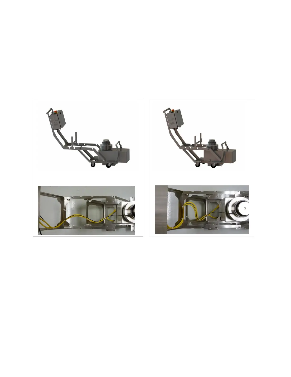
Insert the four carriage screws into four frame connection points. The two side bolts
should go through bushings as shown in Figure 27.
Secure the frame with the four nuts at the connection points. Tighten the nuts. Make
sure the square portion of screw heads are fitted into the square holes in frame.
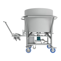
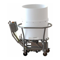
Adjust and clip the cables to the frame to fit the frame configuration as shown in
Figures 25 and 26.
Figure 25: Extended configuration Figure 26: Collapsed configuration
 Loading...