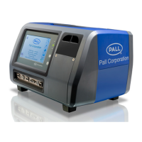
5.3 Operational Checks
Preparation checks before going to the
installation to be sampled.
Caution: The PCM500
display touch sensitive
screen must not be pressed
with a sharp or pointed implement.
Finger contact is sufficient to operate the
display menu icons and keyboard.
Press and release the PCM500 start button
The Control panel green LED
will flash within a few seconds
and the PCM500 enters the
start-up phase. After a short period the
display will turn on and a screen will appear
with Pall logo. The next phase of start-up is
test firing of the internal valves (six clicks).
Following this the main menu screen is
visible.
If the PCM fails to power up on battery,
connect the external PSU and check the blue
LED on the front panel is ON. If not, check or
replace the input fuse with the correct value.
If the PCM fails to start, consult Pall.
First screen
2. If the PCM500 has been used previously
with a different fluid to the new sample then
fluid change procedures detailed in section 7
should be adopted.
3. Switch off the PCM500 and you are now
ready to proceed to the installation to be
sampled.
5.4 Installation Checks
At installation to be sampled
1) Access the hoses at the rear of the
PCM500.
2) Ensure the hose connectors are clean
and free from any visual contaminants.
3) Ensure the installation to be sampled is in
operation and has been running for a
minimum of 30 minutes prior to taking the
sample in order to distribute the
contamination as evenly as possible
within the fluid. This is necessary to allow
a representative fluid sample to be taken.
4) Connect the clear return line hose to the
system reservoir or suitable capacity
container ensuring cap is removed
5) Connect the black hose to the
appropriate sampling point. Check for
any leakage, rectify as required.
Warning: Ensure the
system operating pressure
is within the PCM500
monitor specified limitation of 315 bar,
4,570 psi maximum.
6) The PCM500 can now be switched on
and the screen sequence followed. The
specific procedure for start-up is detailed
in section 5.4 and section 6 ‘Getting
started’.
Section 6: Getting Started
6.1 General
This section of the operating instructions
enables a new user to perform tests using
the PCM500 Cleanliness Monitor in a short
space of time. It does not instruct the user in
sampling techniques and the user should
consult Pall for guidance on recommended
sampling points.
6.2 System Components
• PCM500 Cleanliness Monitor
• Power Supply Unit
• Battery Pack
• Bluetooth / USB Printer (Option)
17

 Loading...