A
B
C
PQRSTU
V
W
X
Y
Z
[
\
^
]
L
M
NO
12
PUSH
HD
RET1
SDI INPUT SDI OUTPUT
RET2 RET3 RET4 OUT1 OUT2 OUT3
OUT4/PM Y / G Pb / B Pr / R PM
HD
OUTPUT
SD
RET1
SDI INPUT SDI OUTPUT
RET2 RET1 RET2
PROMPT
RET3 RET4 OUT1 OUT2 OUT3 OUT4
SD
COMMUNICATION
WFM1
IN RTS
OUT CH–1 CH–2
DIGITAL AUDIO
TRUNK WFM CONTROL
AUX
ROP
CSU / MSU
ALARM
GND
MIC OUT
WFM2 PM1 PM2 VBS1 VBS2 HD HD REFSD
SD
OUTPUT
INPUT 1 2
SYNC OUTPUT
SD REF
AC IN
F
E
GH
I J K
D
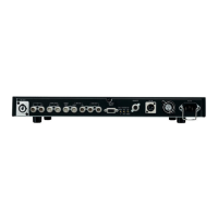
] AC inlet [AC IN]
AC 120 V, 50/60 Hz
^ Ground terminal [GND]
\ Alarm connector [ALARM]
This connector is for outputting the alarm signals to the
external system when any problem with the supply volt-
age has occurred inside the CCU or the CCU fan has
stopped.
When the power supplied to the AC fan or DC fan inside
the CCU has been shut down, pins 3 and 4 of this con-
nector are shorted.
If power is supplied to the CCU and any of the DC power
supplies inside the CCU fails to output the supply voltage,
it means that pins 1 and 2 of this connector are shorted.
Alarm connector (RM-12BRB-4PH made by Hirose)
Pin No. Function
POWER ALARM (H)1
POWER ALARM (L)2
FAN ALARM (H)3
FAN ALARM (L)4
1. Turn off the power of CCU.
2. Turn the knobs and remove the front panel.
3. Switch the SW281 (MODE SW) on the Control board as
follows:
≥ The factory setting is
“
720p camera”.
4. Install the front panel, and turn on the power to complete
setting.

 Loading...