ROP/MSU monitor selection SDTV WFM output
RR
GG
BB
RGB 3 waveformsSEQ
Composite videoENC
Pin
No.
Function
Optical fiber
Polarity Signal flow
CAM#CCU
Cable color
Yellow (01)1
Optical fiber
CCU#CAM
Yellow (02)2
Control wire, hot
i CAM,.CCU
Black3
Control wire, cold
j CAM,.CCU
Red4
AC 240 V live
i CCU#CAM
Orange5
AC 240 V neutral
j CCU#CAM
White6
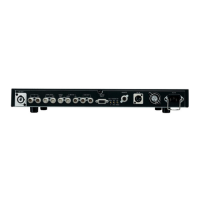
E SDTV digital return video 1, 2, 3, 4 input connectors
[SDTV DIGITAL RET 1, 2, 3, 4]
These connectors are for inputting the return video sig-
nals of the SDTV serial digital interface.
F SDTV D1 digital video output connectors
[SDTV DIGITAL OUT D1 1, 2 3]
These connectors are for outputting the D1 format video
signals of the SDTV serial digital interface.
There are 3 connectors (BNC).
G Analog return video 1, 2 input connectors
[ANALOG RET 1, 2]
These connectors (BNC) are for inputting the SD analog
return video signals.
H PROMPT-IN connectors [PROMPT1,2]
These are the prompter signal input connectors (BNC).
Input SDTV composite video signals as the prompter sig-
nals.
I SDTV waveform monitor output connectors
[SDTV WFM 1, 2]
These connectors (BNC) are for outputting the camera
video signals which are to be displayed on the SDTV
waveform monitor.
B HDTV digital return video 1, 2, 3, 4 input connectors
[HD DIGITAL RET 1, 2, 3, 4] (Option)
These connectors (BNC) are for inputting the return video
signals of the HDTV serial digital interface.
C HDTV digital video 1, 2, 3, 4 output connectors
[HD DIGITAL OUT 1, 2, 3, 4] (Option)
These connectors (BNC) are for outputting the video sig-
nals of the HDTV serial digital interface.
D HDTV analog component video output connectors
[HDTV ANALOG Y/G, Pb/B, Pr/R] (Option)
The HDTV analog signals of the camera are output from
these connectors (BNC).
G/B/R or Y/Pb/Pr video signals can be selected by the
master setup unit (MSU) or remote operation panel
(ROP).
SDTV PM output connector [PM]
This is the HDTV PM output (1Vp-p) connector.
A Optical fiber connector
FXW.3K.93C.CLM made by LEMO

 Loading...