6
Parts and their functions
J SDTV picture monitor video output connectors
[PM 1, 2]
These connectors (BNC) are for outputting the video signals
which are to be displayed on the SDTV picture monitor.
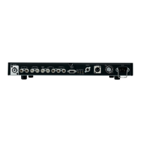
$ Camera control unit rear panel
A
B
C
PQRSTU
V
W
X
Y
Z
[
\
^
]
L
M
NO
12
PUSH
HD
RET1
SDI INPUT SDI OUTPUT
RET2 RET3 RET4 OUT1 OUT2 OUT3
OUT4/PM Y / G Pb / B Pr / R PM
HD
OUTPUT
SD
RET1
SDI INPUT SDI OUTPUT
RET2 RET1 RET2
PROMPT
RET3 RET4 OUT1 OUT2 OUT3 OUT4
SD
COMMUNICATION
WFM1
IN RTS
OUT CH–1 CH–2
DIGITAL AUDIO
TRUNK WFM CONTROL
AUX
ROP
CSU / MSU
ALARM
GND
MIC OUT
WFM2 PM1 PM2 VBS1 VBS2 HD HD REFSD
SD
OUTPUT
INPUT 1 2
SYNC OUTPUT
SD REF
AC IN
F
E
GH
I J K
D
ROP/MSU monitor selection SDTV PM1 output
Rialarm display
R
Gialarm display
G
Bialarm display
B
Y and skin tone zebra patternSEQ
Composite videoENC
K SDTV analog composite video output connectors
[SDTV VBS]
These connectors (BNC) are for outputting the SDTV ana-
log composite video signals (with sync) of the camera.
L HDTV analog SYNC output connector [HD SYNC]
The HDTV analog sync signal of the camera is output
from this connector (BNC). Its amplitude is +/-0.3 V (75h
termination).
M SDTV analog SYNC output connector
[SDTV ANALOG SYNC]
The SDTV analog sync signal of the camera is output
from this connector (BNC). Its amplitude is 2 Vp-p (75h
termination).
N HDTV genlock input connectors [HD REF]
These are the HDTV genlock input connectors (BNC).
The bridging connection between the two connectors
enables one to be used for input purposes and the other
for output purposes.
Input the HDTV tri-level sync signal as the genlock signal.
O SDTV genlock input connectors [SDTV REF]
These are the SDTV genlock input connectors (BNC).
The bridging connection between the two connectors
enables one to be used for input purposes and the other
for output purposes.
Input the BB video signal as the genlock signal.
P INCOM/tally connector [COMMUNICATION]
The external INCOM or tally system is connected here.
INCOM/tally connector (KPT02E14-19P made by Japan
Aviation Electronics Industry)
Pin No. Function
Shield
Polarity Signal flow
A
INCOM 1
CCU#SYSTEM
B
INCOM 1
CCU#SYSTEM
C
INCOM 1
SYSTEM#CCU
D
INCOM 1
SYSTEM#CCU
E
INCOM 2
INCOM 2
INCOM 2
INCOM 2
PGM1(H)
PGM1(C)
PGM2(H)
PGM2(C)
NC
Red tally
Green tally
NC
NC
Tally common
i
j
CCU#SYSTEM
CCU#SYSTEM
SYSTEM#CCU
SYSTEM#CCU
SYSTEM#CCU
SYSTEM#CCU
SYSTEM#CCU
SYSTEM#CCU
Contact
Contact
PGM output level: 0 dBm/600h
INCOM level: 0 dBm/600h
F
G
H
J
K
L
M
N
P
R
S
T
U
V
i
j
i
j
i
j
i
j
i
j

 Loading...