7
Parts and their functions
S T Mic 1, 2 output connectors [MIC OUT CH-1, CH-2]
These are the microphone 1 analog output connectors of
the camera.
The microphone level is 0 dBm/600
h.
Mic output connector (HA16RD-3P made by Hirose)
U Digital audio output connector [DIGITAL AUDIO]
This is the camera microphone 1 and 2 output connector
(BNC) for AES/EBU digital audio interface specifications.
Q RTS input connector [RTS IN]
The RTS system is connected to this connector.
The microphone level is
j4 dBm/200h.
RTS input connector (HA16PRK-3S made by Hirose)
Pin No. Function
Common
Polarity Signal flow
1
Channel 1 (iDC)
2
Channel 23
Pin No. Function
Common
Polarity Signal flow
1
Channel 1 (iDC)
2
Channel 23
R RTS output connector [RTS OUT]
The unit is connected to the RTS system from this con-
nector.
The microphone level is
j4 dBm/200h.
RTS output connector (HA16RD-3P made by Hirose)
Pin No. Function
Shield
Polarity
i
j
Signal flow
CCU#SYSTEM
CCU#SYSTEM
1
Hot2
Cold3
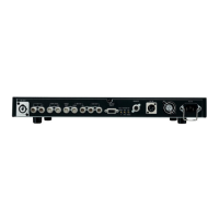
$ Camera control unit rear panel
A
B
C
PQRSTU
V
W
X
Y
Z
[
\
^
]
L
M
NO
12
PUSH
HD
RET1
SDI INPUT SDI OUTPUT
RET2 RET3 RET4 OUT1 OUT2 OUT3
OUT4/PM Y / G Pb / B Pr / R PM
HD
OUTPUT
SD
RET1
SDI INPUT SDI OUTPUT
RET2 RET1 RET2
PROMPT
RET3 RET4 OUT1 OUT2 OUT3 OUT4
SD
COMMUNICATION
WFM1
IN RTS
OUT CH–1 CH–2
DIGITAL AUDIO
TRUNK WFM CONTROL
AUX
ROP
CSU / MSU
ALARM
GND
MIC OUT
WFM2 PM1 PM2 VBS1 VBS2 HD HD REFSD
SD
OUTPUT
INPUT 1 2
SYNC OUTPUT
SD REF
AC IN
F
E
GH
I J K
D

 Loading...