EasyManua.ls Logo

Panasonic AK-HCU931 - Page 9

Panasonic AK-HCU931
16 pages
To Next Page IconTo Next Page
To Previous Page IconTo Previous Page
Loading...
9
[ Fan
This dissipates the heat generated inside the CCU to
keep the unit cool.
Z CSU/MSN connector
The camera selector unit (CSU) is connected to this con-
nector.
CSU connector (HR10A-10R-10S made by Hirose)
Parts and their functions
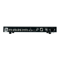
$ Camera control unit rear panel
A
B
C
PQRSTU
V
W
X
Y
Z
[
\
^
]
L
M
NO
12
PUSH
HD
RET1
SDI INPUT SDI OUTPUT
RET2 RET3 RET4 OUT1 OUT2 OUT3
OUT4/PM Y / G Pb / B Pr / R PM
HD
OUTPUT
SD
RET1
SDI INPUT SDI OUTPUT
RET2 RET1 RET2
PROMPT
RET3 RET4 OUT1 OUT2 OUT3 OUT4
SD
COMMUNICATION
WFM1
IN RTS
OUT CH–1 CH–2
DIGITAL AUDIO
TRUNK WFM CONTROL
AUX
ROP
CSU / MSU
ALARM
GND
MIC OUT
WFM2 PM1 PM2 VBS1 VBS2 HD HD REFSD
SD
OUTPUT
INPUT 1 2
SYNC OUTPUT
SD REF
AC IN
F
E
GH
I J K
D
Y ROP connector
The remote operation panel (ROP) is connected to this
connector.
ROP connector (HR10A-10R-10S)
Pin No. Function
ROP CONT (H)
Polarity
i
Signal flow
CCU#ROP
1
ROP CONT (C)
j CCU#ROP
2
ROP DATA (H)
i ROP#CCU
3
ROP DATA (C)
j ROP#CCU
4
POW REM/CD A
CCU#ROP
5
INCOMT/CD B
INCOMR/CD C
INCOMG/CD D
i12V
GND
i
CCU#ROP
CCU#ROP
CCU#ROP
CCU#ROP
6
7
8
9
10
Pin No. Function
CSU DATA (H)
Polarity
i
Signal flow
CCU#CSU
1
CSU DATA (C)
j
CCU#CSU
2
CSU CONT (H)
i
CSU#CCU
3
CSU CONT (C)
j
CSU#CCU
4
TALLY R
CCU#CSU
5
TALLY G
HEAD POWER
ALARM 1
ALARM 0
GND
CCU#CSU
CCU#CSU
CCU#CSU
CCU#CSU
6
7
8
9
10

Related product manuals