43
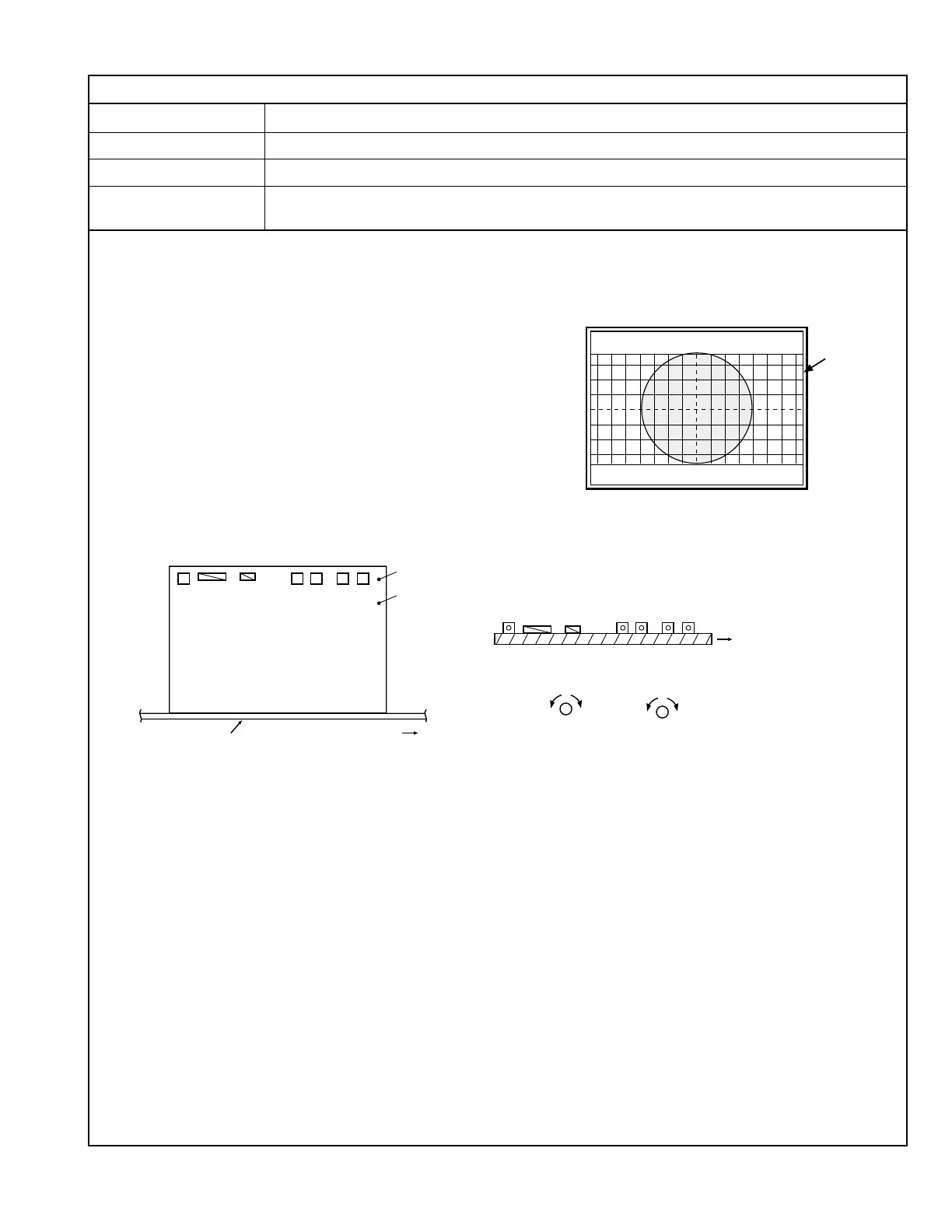
CONVERGENCE ADJUSTMENT
Measuring Instruments Signal generator (Crosshatch signal with circle pattern)
Card (Slot) Component/RGB Input Card (Slot 1)
Test Points
Adjustment Points VR504 (CONV_H) [S. CORRECTION PWB]
VR505 (CONV_V) [S. CORRECTION PWB]
Notes: • Perform the following adjustments after completing the Screen Volt-
age, X-Ray Protector, High Voltage and Focusing adjustments.
• Ensure that CN0RD and CN00R on the S. Correction PWB are con-
nected to the Deflection yoke and Main Board.
1. Apply the 1080/60i crosshatch signal with circle pattern to INPUT A (Terminal Y
on the Component/RGB Input Card).
2. Turn the VR504 to optimize the horizontal convergence value at the center of the
screen (turning the potentiometer counterclockwise shifts BLUE toward the right
with respect to RED).
3. Turn the VR505 to optimize the vertical convergence value at the center of the
screen (turning the potentiometer counterclockwise shifts BLUE downward with
respect to RED).
CONVERGENCE ADJUSTMENT
S. CORRECTION PWB
MAIN PWB
Front side
TP-XR
TP-G
Front side
(Left) (Right)
(Upper)(Lower)
VR503 [ROTATION]
VR505 [CONV_V]
VR504 [CONV_H]
VR502 [H.VOLTAGE]
VR501 [X-RAY]
CN0RD
CN00R
(Top surface view of S. CORRECTION PWB)
VR505
VR504
VR503
VR505
VR504
VR502
VR501
CN0RD
CN00R
 Loading...