5
4 Technical Descriptions
4.1. Terminals Description
4.1.1. Main Block
IC601 : YESAM388
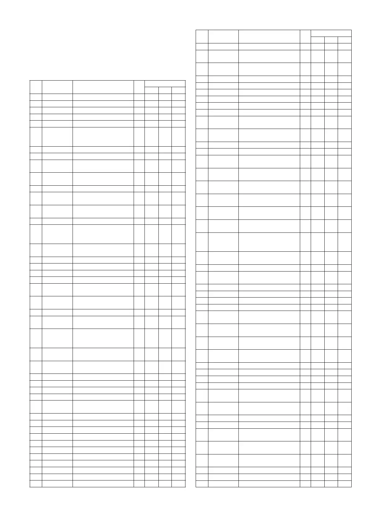
Pin
No
Port Description I/O Vol [V]
FM AM CD
1 DBGP0 Not connected - - - -
2 DBGP1 Not connected - - - -
3 DBGP2 Not connected - - - -
4 RDS CLK Not connected - - - -
5 RM DATA Remote control data I 4.7 4.7 4.7
6 CDC STB/
SYSID4
CD changer Strobe; or
Hub connection device
identification 4
I000
7 EVENT Hub event detection I 0 0 0
8 RESET System reset I 4.7 4.7 4.7
9 XT1 Crystal oscillator 1
(32.768kHz)
I111
10 XT2 Crystal oscillator 2
(32.768kHz)
O 1.4 1.4 1.4
11 VSS Ground - 0 0 0
12 CF1 Ceramic oscillator 1
(13.5MHz)
I 1.4 1.4 1.4
13 CF2 Ceramic oscillator 2
(13.5MHz)
O 1.3 1.3 1.3
14 VDD +5V power supply - 4.8 4.8 4.8
15 INT A Pulled up for CQ-C5405U;
Pulled down for CQ-
C5305U
I 4.8 4.8 4.8
16 VSM Signal meter intensity
(Tuner)
I 0.2 0 0.2
17 INT B Pulled down to GND - 0 0 0
18 LEVEL Not connected - - - -
19 N.C. Not connected - - - -
20 ACC ACC level detection I 4.9 4.9 4.9
21 SYSID1 Hub connection device
identification 1
I 4.8 4.8 4.8
22 SYSID2 Hub connection device
identification 2
I 4.8 4.8 4.8
23 N.C. Not connected - - - -
24 CDC DATA Serial data from CD
changer
I000
25 CDC CLK/
SYSID3
Serial clock for CD
changer; or Hub connec-
tion device identification 3
I000
26 CD DI (CD
SI)
Serial data from CD I 0 0 0
27 CD DO (CD
SO)
Serial data to CD O 0 0 0.6
28 CD CLK Serial clock for CD O 4.4 4.4 4.4
29 CD CE (FS) CD chip enable O 4.6 4.6 3.2
30 CD MUTE CD mute I 3.2 3.2 0
31 CD RST CD reset O 4.8 4.8 4.8
32 POWER
CNT
System power supply con-
trol
O 4.8 4.8 4.8
33 N.C. Not connected - - - -
34 N.C. Not connected - - - -
35 CD SW1 CD detection switch 1 I 0 0 0
36 CD SW2 CD detection switch 2 I 0 0 0
37 N.C. Not connected - - - -
38 N.C. Not connected - - - -
39 VSS Ground - 0 0 0
40 VDD +5V power supply - 4.8 4.8 4.8
41 N.C. Not connected - - - -
42 N.C. Not connected - - - -
43 N.C. Not connected - - - -
44 N.C. Not connected - - - -
45 HUB ACC
CNT
Power supply control for
Hub (CD changer)
O0 0 0
46 HUB CNT Hub connection check
request
O4.84.84.8
47 INV CNT Not connected - - - -
48 N.C. Not connected - - - -
49 LCD DI Serial data to LCD O 4.7 4.7 4.7
50 LCD DO Serial data from LCD I 4.6 4.6 4.6
51 LCD CLK Serial clock for LCD O 4.8 4.8 4.8
52 LCD CE Chip enable for LCD CPU O 0 0 0
53 E-VOL I2C
DATA
Serial data for Audio signal
processor (volume)
O4.84.84.8
54 E-VOL I2C
CLK
Serial data for Audio signal
processor
O4.84.84.8
55 VDD +5V power supply - 4.8 4.8 4.8
56 VSS Ground - 0 0 0
57 E-VOL LV
CLK
Serial clock to Audio signal
processor (Audio level)
O0 0 0
58 E-VOL LV
DATA
Serial data from Audio sig-
nal processor (Audio level)
I000
59 STBY Standby mode for Power
amplifier
O4.84.84.8
60 SRS MODE
1
Not connected - - - -
61 SRS MODE
2
Not connected - - - -
62 SRS MODE
3
Not connected - - - -
63 SRS
FOCUS
ELVL
Not connected - - - -
64 EJ ILL Ejection key illumination
control
O4.84.84.8
65 PANEL IN Front panel detection I 0 0 0
66 LCD 5V CNT +5V power supply control
for LCD circuit
O0 0 0
67 N.C. Not connected - - - -
68 EJECT Ejection switch I 4.8 4.8 4.8
69 BATT Battery level detection I 4.8 4.8 4.8
70 EXT MUTE Telephone mute I 4.8 4.8 4.8
71 OP/CL Open/Close detection for
Front panel
I4.64.64.6
72 MODE B
(ROTARY 2)
Rotary encoder detection
B for volume
I4.84.84.8
73 MODE A
(ROTARY 1)
Rotary encoder detection
A for volume
I4.84.84.8
74 CDC REM
OUT
Remote control for CD
changer
O0 0 0
75 HUB-TX Transmission data to Hub O 0 0 0
76 HUB-RX Reception data from Hub I 0 0 0
77 N.C. Not connected - - - -
78 N.C. Not connected - - - -
79 FM MODE Power supply control for
FM mode
O4.8 0 4.8
80 AM MODE Power supply control for
AM mode
O04.80
81 MONO Not connected - - - -
82 ST FM stereo indication I 4.8 4.8 4.8
83 EE-PROM
DI/DO
Serial data for EEPROM I/O 0 0 0
84 EE-PROM
CS
Chip select for EEPROM O 0 0 0
85 EE-PROM
SK
Serial clock for EEPROM O 0 0 0
86 ANT CNT Not connected - - - -
87 VREG Connected to capacitor - 3 3 3
88 VSS Ground - 0 0 0
Pin
No
Port Description I/O Vol [V]
FM AM CD
 Loading...