Pin
No.
Port Description (I/O) (V)
FM AM CD
98 SLED Security LED control
output
O 0 0 5
99 PANEL IN PANEL detect I 5.2 5.2 5.2
100 EP CS(NC) No Connection - - - -
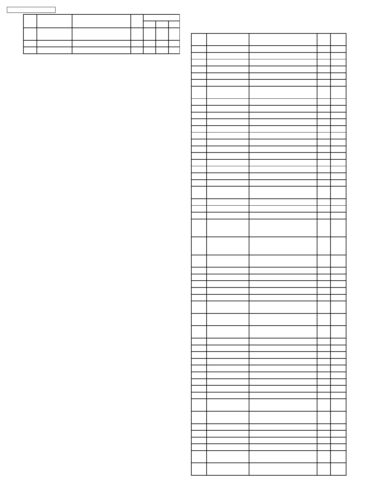
11.2. Display Block
IC900 C2CBJH000095
Pin
No.
Port Part Name & Description I/O (V)
1 A18 FLASH A17 O 1.5
2 A19 FLASH A18 O 1.7
3 A20 FLASH A19 O 1.3
4 NC No Connection - -
5 NC No Connection - -
6 NC No Connection - -
7 A0 LCD driver data or command
distinction
O 1.3
8 A1 FLASH A0 O 0.3
9 VSS Ground potential - 0
10 A2 FLASH A1 O 0.4
11 A3 FLASH A2 O 0.4
12 A4 FLASH A3 O 0.4
13 A5 FLASH A4 O 1.3
14 A6 FLASH A5 O 0.4
15 A7 FLASH A6 O 0
16 A8 FLASH A7 O 1.3
17 A9 FLASH A8 O 0
18 A10 FLASH A9 O 0
19 A11 FLASH A10 O 1.5
20 A12 FLASH A11 O 1.7
21 VCC Positive power supply
terminal
- 3.5
22 A13 FLASH A12 O 1.4
23 A14 FLASH A13 O 1.6
24 A15 FLASH A14 O 1.7
25 SUB SI UP SO MAIN-u-com communication
data input and external flash
rewritting
- 0.5
26 SUB SO/UP SI MAIN-u-com communication
data output and external
flash rewritting
O 1.8
27 UP CLK External flash rewritting
switch
I 3.5
28 NC No Connection - -
29 FLASH RESET FLASH reset control output O 3.5
30 KS1 Key scan signal 1 output I 0
31 NC No Connection - -
32 NC No Connection - -
33 AVCC Positive power supply for A/D
converter
- 3.5
34 AVRH A/D converter standard
voltage input
- 3.5
35 AVSS/AVRL A/D converter ground
potential
- 0
36 TH DETECT Temperature detection input I 1.3
37 KS2 Key scan signal 2 output I 0
38 KS3 Key scan signal 3 output I 0
39 NC No Connection - -
40 VSS Ground potential - 0
41 KI5 Key return signal 5 input I 0
42 KI4 Key return signal 4 input I 0
43 KI3 Key return signal 3 input I 0
44 KI2 Key return signal 2 input I 0
45 NC FLASH writing program
starter
I 0
46 NC FLASH writing program
starter
I 3.5
47 MD0 Mode setting terminal I 3.5
48 MD1 Mode setting terminal I 3.5
49 MD2 Mode setting terminal I 0
50 S W U REQ SUB-u-com wake up request INT 3.0
51 ROTARY.1 Rotary encoder signal 1(VOL
UP)
I 2.5
52 ROTARY.2 Rotary encoder signal 2 (VOL
DOWN)
I 2.5
14
CQ-C8401W / CQ-C7401W
 Loading...