Do you have a question about the Panasonic CS-C18DKD and is the answer not in the manual?
| Brand | Panasonic |
|---|---|
| Model | CS-C18DKD |
| Category | Air Conditioner |
| Language | English |
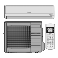
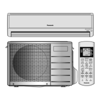
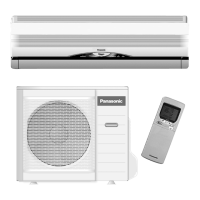
Details the functions and operation of the remote control unit.
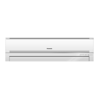
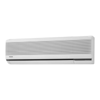
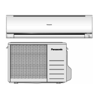
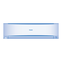
Explains the features and operation of the indoor unit.
Describes the components and operation of the outdoor unit.
Lists detailed technical specifications for the CS-C18DKD CU-C18DKD model.
Lists detailed technical specifications for the CS-C24DKD CU-C24DKD model.
Provides dimensional drawings and measurements for the indoor unit and remote.
Details the dimensions and installation space for the outdoor unit.
Presents the electrical wiring diagram for the CS-C18DKD CU-C18DKD model.
Presents the electrical wiring diagram for the CS-C24DKD CU-C24DKD model.
Explains cooling, soft dry, and automatic operation modes and their principles.
Details indoor fan speed control and vertical/horizontal airflow direction adjustments.
Describes powerful, quiet, and ionizer operations for enhanced user experience.
Covers timer settings, auto restart, and remote signal sound functions.
Outlines essential safety warnings and precautions for operation.
Provides critical safety warnings related to the installation process.
Lists mandatory precautions to follow during the operation of the unit.
Details safety regulations and recommended operating temperature ranges.
Overview of the indoor unit's main components and features.
Overview of the outdoor unit's main components and features.
Overview of the remote control and its preparation and functions.
Summary of common issues and troubleshooting steps.
Guides on cleaning the front panel, air filter, supersonic device, and ionizer.
Specific instructions and warnings for washing unit components.
Procedures for extended non-operation and pre-season inspections.
Critical safety warnings and guidelines for installation work.
Step-by-step procedures for selecting location and installing the indoor unit.
Procedures for selecting the location and installing the outdoor unit.
Instructions for evacuating air and charging refrigerant during installation.
Procedures for purging air from the piping and indoor unit.
Steps for pumping down the refrigeration system.
Instructions for re-purging air, typically for re-installation.
Procedure to balance refrigerant levels using 3-way valves.
Steps for evacuating the system when no refrigerant is present.
Procedure for charging refrigerant into the system after evacuation.
Guides on how to remove electronic controllers from the indoor unit.
Procedures for removing the cross flow fan and indoor fan motor.
Instructions for resetting the remote control unit.
Explains the auto OFF/ON button functions and setting modes.
Guide to diagnosing malfunctions related to the refrigeration cycle.
Methods for diagnosing compressor malfunctions.
Data on thermostat settings and their effect on operation.
Performance data including cooling capacity and current.
Visual breakdown of indoor unit parts for disassembly and replacement.
Comprehensive list of replacement parts for the indoor unit.
Visual breakdown of CU-C18DKD outdoor unit parts for disassembly.
Visual breakdown of CU-C24DKD outdoor unit parts for disassembly.
Comprehensive list of replacement parts for the outdoor unit.
Detailed electronic circuit diagrams for indoor and outdoor units.
Provides the electronic circuit diagram for the wireless remote control.
Shows the print pattern layout for the indoor unit's printed circuit board.
Shows the print pattern for the indicator and receiver PCB.