53
10.5.6. Heat insulation
10.5.7. Charging with refrigerant
• At the time of shipment from the factory, this unit is charged with enough refrigerant for an equivalent pipe length of max charge-
less lenght. (Refer table below)
If the equivalent pipe length will be up to max charge-less length, no additional charging will be necessary.
• If the equivalent pipe length will max charge-less length, charge with additional refrigerant according to the equivalent length
given in the table below.
Example: CU-D24DBQ6
In case of 50m equivalent length, the amount of refrigerant to be replenished is: (50 - 30) x 0.025 = 0.5kg
• Pump down operation
- Operate the pump down according to the following procedures.
10.5.8. Electrical wiring
• Connect the power supply wiring and indoor/outdoor unit connection wiring according to the electrical circuit diagram instruc-
tions.
• Clamp the wires securely to the terminal connections using cord clamps so that no undue force is placed on the wires.
• Once all wiring work has been completed, tie the wires and cords together with the binding strap so that they do not touch other
parts such as the compressor and pipes.
Caution
Use a material with good heat-resistant properties as the
heat insulation for the pipes. Be sure to insulate both the
gas-side and liquid-side pipes. If the pipes are not ade-
quately insulated, condensation or water leakages may
occur.
Liquid-side pipes Material that can withstand
Gas-side pipes 120°C or higher
Model name Power supply frequency Equivalent length Additional amount
Mac charge-less length Max equivalent length
CU-D24DBQ6
CU-D28DBQ6
60Hz 30m 50m 0.025kg/m
CU-D34DBQ7
CU-D43DBQ7
CU-D50DBQ7
50Hz 20m 40m 0.04kg/m
50Hz 30m 50m
Procedure Notes
1. Confirm the valve on the liquid side and the gas side is surely open.
2. Press the PUMP DOWN switch on outdoor printed board for 1 second
or more.
Perform the cooling operation for five minutes or more.
3. Shut the valve on the liquid side surely. When the valve is shut halfway, the compressor is occasionally dam-
aged.
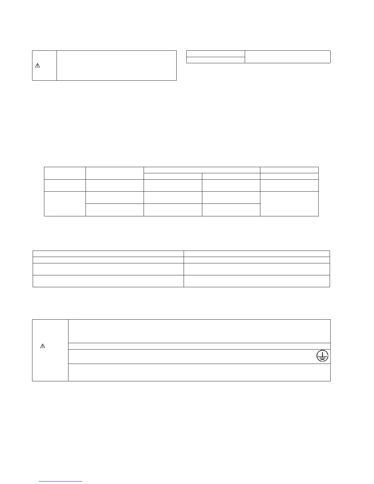
Warning
The units must be connected to the supply cables for fixed wiring by qualified technician.
Feed the power source to the unit via a distribution switch board designed for this purpose, the switch should disconnected all
poles with a contact separation of at least 3mm.
When the supply cable is damaged, it must be replaced by qualified technician.
Be sure to install a current leakage breaker, main switch and fuse to the main power supply, otherwise electric shocks may result.
Be sure to connect the unit to secure earth connection.
If the earthing work is not carried out properly, electric shocks may result.
Wiring shall be connected securely by using specified cables and fix them securely so that external force of the cables may not
transfer to the terminal connection section.
Imperfect connection and fixing leads to fire, etc.
 Loading...