2
4 Location of Controls and Components------------------ 11
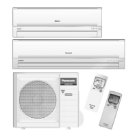
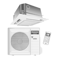
4.1. Product Overview ---------------------------------------- 11
5 Dimensions ------------------------------------------------------- 13
5.1. Indoor Unit -------------------------------------------------13
5.2. Outdoor Unit----------------------------------------------- 14
6 Refrigeration Cycle Diagram -------------------------------- 15
6.1. CS-E15GKEW CU-E15GKE-1-----------------------15
6.2. CS-E15GKEW CU-E15GKECS-E15GKE-3
CU-E15GKE-3 --------------------------------------------16
7 Block Diagram ---------------------------------------------------17
7.1. CS-E15GKEW CU-E15GKE-1-----------------------17
7.2. CS-E15GKEW CU-E15GKECS-E15GKE-3
CU-E15GKE-3 --------------------------------------------18
8 Wiring Connection Diagram --------------------------------19
8.1. Indoor Unit -------------------------------------------------19
8.2. Outdoor Unit----------------------------------------------- 20
9 Electronic Circuit Diagram-----------------------------------22
9.1. Indoor Unit -------------------------------------------------22
9.2. Outdoor Unit----------------------------------------------- 23
10 Printed Circuit Board ------------------------------------------25
10.1. Indoor Unit -------------------------------------------------25
10.2. Outdoor Unit----------------------------------------------- 27
11 Installation Instruction ----------------------------------------29
11.1. CS-E15GKEW CU-E15GKE-1-----------------------29
11.2. CS-E15GKEW CU-E15GKECS-E15GKE-3
CU-E15GKE-3-------------------------------------------- 36
12 Operation and Control---------------------------------------- 43
12.1. Basic Function-------------------------------------------- 43
12.2. Protection Control --------------------------------------- 53
13 Servicing Mode-------------------------------------------------- 57
13.1. Auto OFF/ON Button ----------------------------------- 57
13.2. Select Remote Control Transmission Code------- 57
13.3. Remote Control Button--------------------------------- 58
14 Troubleshooting Guide--------------------------------------- 59
14.1. Refrigeration Cycle System--------------------------- 59
14.2. Breakdown Self Diagnosis Function---------------- 61
14.3. Error Codes Table --------------------------------------- 62
15 Disassembly and Assembly Instructions -------------- 64
15.1. Indoor Electronic Controllers, Cross Flow Fan
and Indoor Fan Motor Removal Procedures------ 64
15.2. Outdoor Electronic Controller Removal
Procedure-------------------------------------------------- 68
16 Technical Data --------------------------------------------------- 70
16.1. Operation Characteristics ----------------------------- 70
16.2. Sensible Capacity Chart ------------------------------- 78
17 Exploded View and Replacement Parts List----------- 79
17.1. Indoor Unit------------------------------------------------- 79
17.2. Outdoor Unit ---------------------------------------------- 81
1 Safety Precaution
• Read the following “SAFETY PRECAUTIONS” carefully before perform any servicing.
• Electrical work must be installed or serviced by a licensed electrician. Be sure to use the correct rating of the power plug and
main circuit for the model installed.
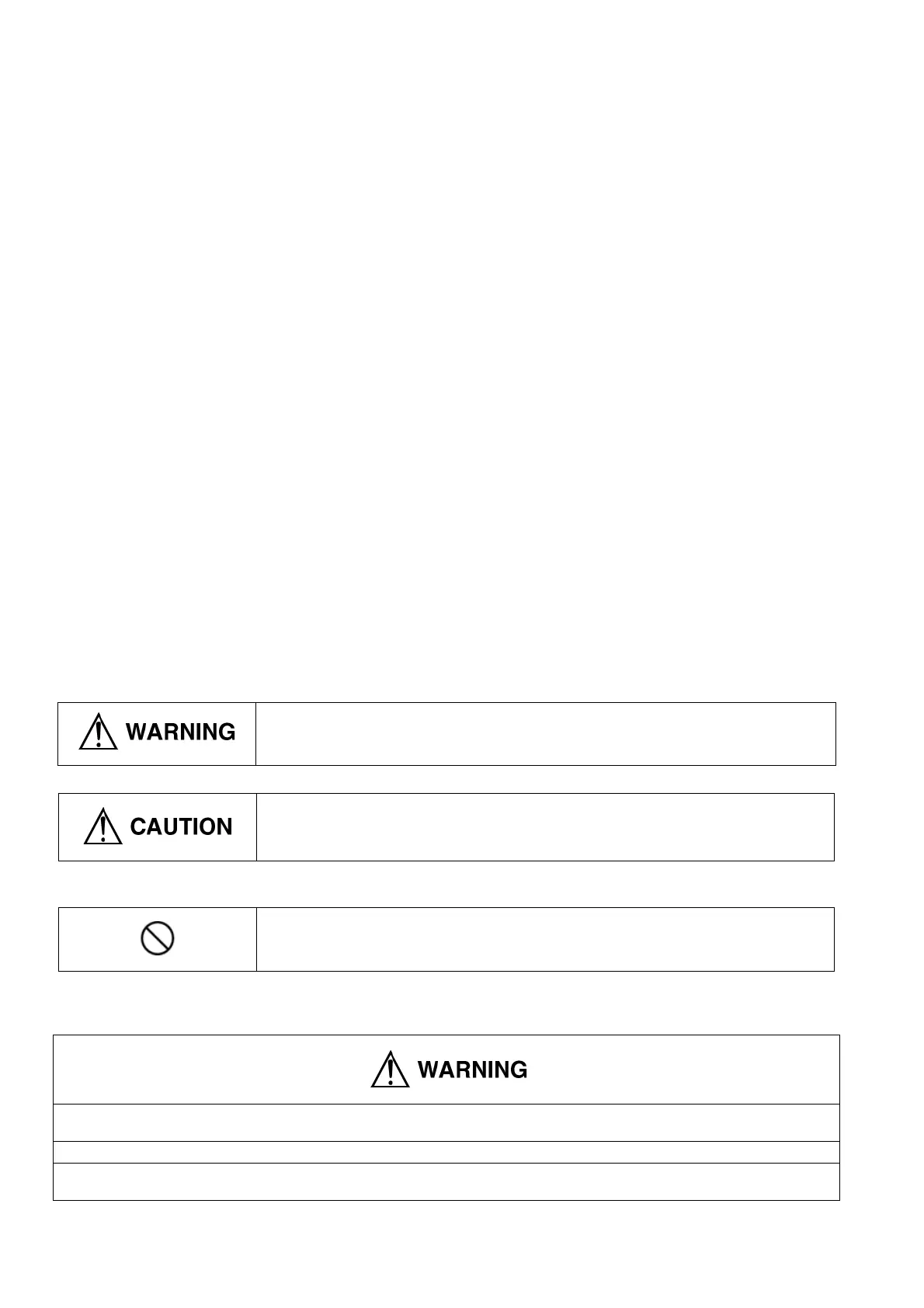
• The caution items stated here must be followed because these important contents are related to safety. The meaning of each
indication used is as below. Incorrect installation or servicing due to ignoring of the instruction will cause harm or damage, and
the seriousness is classified by the following indications.
• The items to be followed are classified by the symbols:
• Carry out test running to confirm that no abnormality occurs after the servicing. Then, explain to user the operation, care and
maintenance as stated in instructions. Please remind the customer to keep the operating instructions for future reference.
This indication shows the possibility of causing death or serious injury.
This indication shows the possibility of causing injury or damage to properties.
This symbol denotes item that is PROHIBITTED from doing.
1. Engage dealer or specialist for installation and servicing. If installation or servicing done by the user is defective, it will cause water
leakage, electrical shock or fire.
2. Install according to this installation instruction strictly. If installation is defective, it will cause water leakage, electrical shock or fire.
3. Use the attached accessories parts and specified parts for installation and servicing. Otherwise, it will cause the set to fall, water leakage,
fire or electrical shock.