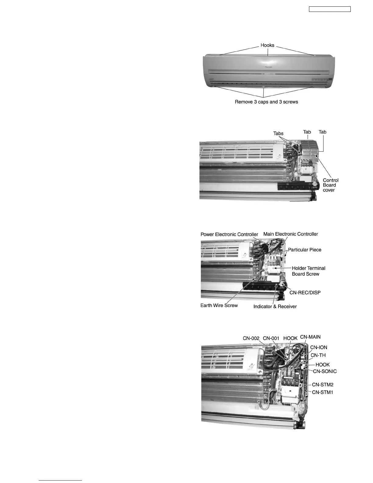
1. The Electronic Controller, a Signal Receiver and an
Indicator (Fig. 3) can be seen by the below steps:
•
Remove the 3 caps and 3 screws at the bottom of the
Front Grille. (Fig. 1)
•
Remove the Front Grille by releasing the 3 hooks at the
top of the Front Grille. (Fig. 1)
•
Unhook the tabs at the Control Board to remove the
Control Board Cover. (Fig. 2)
2. To remove the Main Electronic Controller:
•
Release the earth wire screw. (Fig. 3)
•
Release the Holder Terminal Board screw. (Fig. 3)
•
Release the CN-REC/DISP connector. (Fig. 3)
•
Release the 2 Particular Piece. (Fig. 3)
•
Release the CN-ION connector. (Fig. 4)
•
Release the CN-SONIC connector. (Fig. 4)
•
Release the CN-TH connector. (Fig. 4)
•
Release the CN-MAIN connector. (Fig. 4)
•
Release the CN-STM1 connector. (Fig. 4)
•
Release the CN-STM2 connector. (Fig. 4)
•
Release the hook that hold the Main Electronic
Controller. (Fig. 4)
3. To remove the Power Electronic Controller:
•
Release the CN-001 connector. (Fig. 4)
•
Release the CN-002 connector. (Fig. 4)
•
Release the hook that hold the Power Electronic
Controller. (Fig. 4)
Fig. 1
Fig. 2
Fig. 3
Fig. 4
12.5. Indoor Electronic Controllers Removal Procedures
73
CS-E24DKE CU-E24DKE